Touch electricity and learn easy way!
This Simple School Project Multimeter Circuit show how current and voltage work in real life.
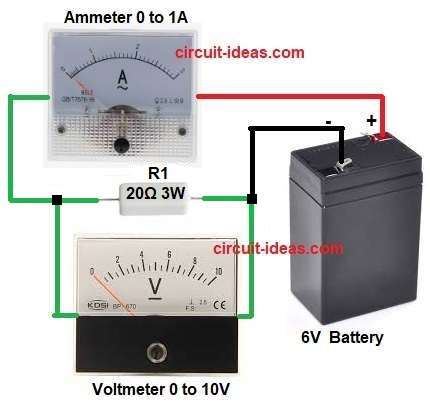
With one battery, one resistor, one ammeter and one voltmeter, we can measure electricity at home.
It is fun, simple and good for beginner to see how circuit really flow.
Circuit Working:
Parts List:
| Parts Name | Value | Quantity |
|---|---|---|
| Resistor | 20Ω 3 watt | 1 |
| Semiconductors | Ammeter 0 to 1A DC | 1 |
| Voltmeter 0 to 10V DC | 1 | |
| Battery 6V DC | 1 |
In this circuit the battery gives the supply.
Ammeter (A) is connected in series with the resistor.
Voltmeter (V) is connected across the resistor in parallel.
This setup helps to measure both current and voltage at the same time.
When the battery is connected, current flows through the resistor.
Ammeter shows how much current is flowing.
Voltmeter shows the voltage drop across the resistor.
Using both readings we can find resistance using Ohms Law.
Formulas with Calculations:
Below is the formula with calculation for Multimeter Circuit:
Ohms Law: V = I × R
So Resistance R = V / I
Example: If voltmeter shows 6V and ammeter shows 0.3A
Then R = 6 / 0.3 = 20 ohms
How to Build:
To build a Simple School Project Multimeter Circuit follow the connections steps:
- Assemble all the parts as shown in circuit diagram
- Connect battery positive to ammeter positive.
- Then connect ammeter negative to one side of resistor.
- Now connect other side of resistor to battery negative to circuit make one loop.
- Next connect voltmeter in parallel and one wire each side of resistor.
- Check all wire are good before switching on the battery.
Conclusion:
This Simple School Project Multimeter Circuit show how to measure voltage and current.
It is easy science project for students.
It help to learn how ammeter and voltmeter work with Ohms law.
This small circuit good for basic experiment and learning electronics.