This Simple Voltage Splitter Circuit using uA741 Op-Amp is a useful and easy project to make; it split one power supply to two equal parts and make virtual ground in middle.
Also, circuit is good for project that need two power supplies but have only one power source and current depends on op-amp specifications.
Here, the circuit is good for only for small load which should be less than 40mA and op-amp keep voltage split steady and equal.
Circuit Working:
Parts List:
| Components | Values | Quantity |
|---|---|---|
| Resistor | 100k 1/4 watt | 2 |
| Semiconductor | IC uA741 Op-Amp | 1 |
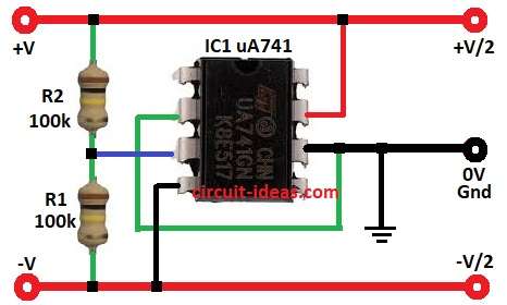
This circuit take one power supply and split in two equal parts like +V/2 and -V/2 and main part is uA741 op-amp which works like buffer to keep steady voltage in middle point.
Also, two resistors R1 and R2 of 100k each make voltage divider for middle voltage V/2 and this middle voltage goes to pin 3 of non-inverting input of op-amp.
Then op-amp work like voltage follower and output pin 6 copy voltage on pin 3 and feedback keep output exactly at V/2; therefore op-amp output is low impedance and it can give or take small current and keep virtual ground steady.
Formulas with Calculations:
Voltage Divider formula:
Vmid = Vsupply × (R2 / (R1 + R2))
where,
- Vmid is middle voltage from resistors R1 and R2
- Vsupply is supply voltage
- R1 and R2 are voltage divider resistors
here, R1 = R2 = 100k so:
Vmid = Vsupply × (100k / (100k + 100k)) = Vsupply / 2
Op-amp voltage follower gain:
Vout = Vin
where,
- Vout is output voltage
- Vin input voltage
Op-amp is in voltage follower mode so output voltage remains equal to input voltage at non-inverting pin.
How to Build:
To build a Simple Voltage Splitter Circuit using uA741 Op-Amp follow the below mentioned steps for connections and assembling:
- First, gather all parts like circuit shows above
- Next, connect pin 2 (inverting input) of IC1 to pin 6 (output) to make voltage follower.
- After that, connect pin 3 (non-inverting input) of IC1 between resistors R1 and R2 form voltage divider.
- Now connect pin 4 of IC1 to -V/2.
- Also, connect pin 6 (output) of IC1 to 0V to create the virtual ground
- Further, connect pin 7 of IC1 to +V/2.
- Finally, connect resistors R1 and R2 in series from +V to -V.
Conclusion:
Overall, this Simple Voltage Splitter Circuit using uA741 Op-Amp make steady virtual ground and split supply to two equal parts.
Also, circuit is good when we need dual power supply but have only one source and then op-amp keep output low impedance and stable and is good for analog circuits.
Leave a Reply