This article is about simple SCR tester circuit, where we can use this circuit to check SCR is good or faulty.
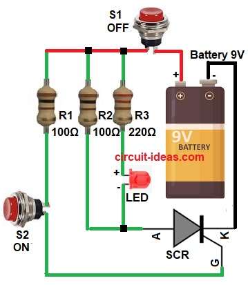
The circuit uses one 9V battery, one LED, three 100 ohm resistors and two push button switches.
The circuit is very easy to build as it is also very useful for students, hobby users and basic electronics testing work.
First, the circuit takes supply from 9V battery and then it sends small trigger current to SCR gate terminal and after that, if SCR is good then it turns ON and a LED glows, so by checking LED we can easily know SCR condition.
Circuit Working:
Parts List:
| Components | Values | Quantity |
|---|---|---|
| Resistors | 100Ω 1/4 watt | 2 |
| 220Ω 1/4 watt | 1 | |
| Semiconductors | Any general purpose SCR | 1 |
| OFF/RESET Normally Closed Push Button Switch | 1 | |
| ON / TEST Normally Open Push Button Switch | 1 | |
| Any standard color LED | 1 | |
| Battery 9V | 1 |
First, connect SCR to three test terminals.
A = Anode
K = Cathode
G = Gate
Now press RESET/OFF switch S1 and this gives power from 9V battery to circuit, but at first the SCR stays OFF and so LED does not glow.
Next, press TEST/ON switch S2 and this switch sends trigger current through resistor R1 to gate terminal G of SCR.
When SCR gets enough gate current and then it turns ON.
After that, current flows from battery positive through resistor R3, LED, SCR anode to cathode and then goes back to battery negative, so LED glows.
Also, when we release TEST/ON switch then SCR still stays ON and this happens because SCR has latching property, so LED keeps glowing.
Then when we press RESET/OFF switch again or remove supply then current stops and SCR turns OFF and LED also goes OFF.
Therefore, this circuit easily checks SCR latching action.
How to Build:
How to Test SCR using LED and 9V Battery Circuit follow the below steps for connections:
- Start, by assembling all the circuit parts as in diagram above.
- Next, start with battery connection and battery positive terminal to RESET/OFF switch S1 input.
- And battery negative terminal goes to terminal K cathode pin line of SCR.
- Then take resistor R1 one side connect to the positive rail and other side of R1 connect to TEST/ ON switch S2.
- From TEST/ON switch output connect to gate terminal point G of SCR.
- Then take resistor R2 one side connect to positive rail and other side connect to anode pin terminal point A.
- After that, take resistor R3 one side connect to positive rail and other side connect to LED anode and LED cathode connect to SCR anode terminal line A.
- Switch S1 RESET/OFF switch connect in series with battery positive line.
- And switch S2 TEST/ON switch connect between R1 and gate terminal G of SCR.
Conclusion:
At Last, this simple SCR tester circuit gives an easy and low-cost way to test any SCR, first it checks gate triggering, next it checks latching action and finally, it confirms whether the SCR stays ON after trigger.
Because the circuit uses very few components, anyone can build it easily on breadboard or PCB and also students can use it for learning SCR working principle in practical form.
Therefore, this circuit is a very good basic electronic testing project for home, lab and educational use.
Leave a Reply