To begin with, main purpose of Simple DC Over Voltage Protector Circuit is to save electronic parts or circuits from damage when voltage from DC power source become too high.
Also, this type of circuit works very well in many applications that need stable and fixed voltage.
Circuit Working:
Parts List:
| Components | Values | Quantity |
|---|---|---|
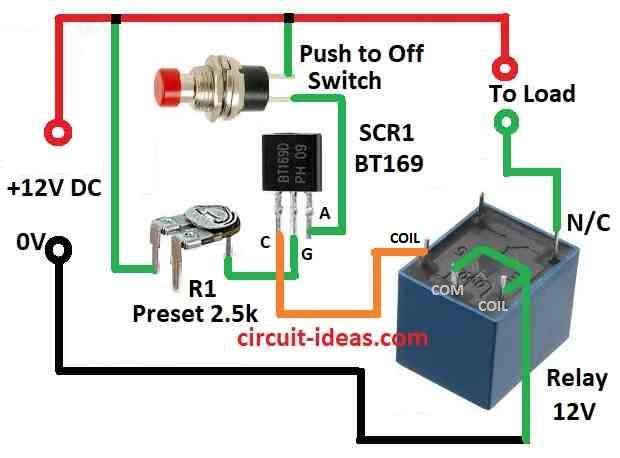
| Variable resistor | Preset 2.5k | 1 |
| Semiconductors | SCR BT169 | 1 |
| Relay 12V | 1 | |
| Push to Off Switch | 1 |
Firstly, the circuit connects a normally closed 12V relay with an SCR, and the SCR stays on the 12V supply line.
Then, the SCR gate section checks the voltage level, when the voltage stays below the limit, SCR1 does not turn ON but the relay remains closed, so current flows to the load.
But when voltage goes above 12V SCR1 gate get enough current.
Then SCR1 turns ON, relay also turn ON and break the current to load and this stop extra voltage go to load and protect it from damage.
Also, R1 sets the voltage level at which SCR1 should turn ON, when SCR1 turns ON, the relay opens and stops the current flow to the load.
Below are few formulas for DC Over Voltage Protection Circuit which need some calculation like this:
1. Voltage Divider Calculation:
To turn ON the SCR we use voltage divider to get one reference voltage (Vref) and we use one fixed resistor (Rf) and one preset resistor (Rp) like this:
Vref = Vin × Rp / (Rp + Rf)
- Vref is the voltage we want to turn ON SCR.
- Vin is the input voltage, in our circuit it is 12V.
- Rp is the preset resistor.
- Rf is the fixed resistor both in series
2. Gate Resistor for SCR:
Also, we need to give correct current to SCR gate to turn it ON and for that we need to use resistor Rg.
Further, we can find the gate current (Ig) in the SCR datasheet and it normally stays between 10 mA and 50 mA.
Ig = (Vgate − Vref) / Rg
So to find Rg:
Rg = (Vgate − Vref) / Ig
- Vgate is the voltage at gate which is normally 1 to 2V.
- Vref is the voltage from divider.
- Ig is the current from datasheet.
- Rg is the resistor we calculate.
3. Relay Coil Current:
Relay coil need enough current to turn ON so we need to heck if SCR can give this current.
Irelay = Vsupply / Rcoil
- Vsupply is the 12V relay power.
- Rcoil is the resistance of relay coil.
- Irelay is the current that go in coil.
4. SCR Power Dissipation:
Check how much power the SCR is using when ON.
PSCR = VT × Iload
- VT is the voltage drop on SCR when ON from datasheet which is usually 1 to 2V.
- Iload is the current through load or relay.
- PSCR is the power SCR is using.
Also, use these formulas to design good circuit, but always check with actual parts and datasheet to be sure.
Furthermore, adjust values based on our component rating.
How to Build:
To build a Simple DC Over Voltage Protector Circuit follow the below steps for connections and assembling:
- First, connect positive side of 12V power to one side of load and connect other side of load to NC Normally Closed contact of relay.
- After that, connect common pin of relay back to positive of 12V supply.
- Then, connect the anode of SCR1 to the point where the load and relay contact join, and connect the cathode of SCR1 to the negative side of the 12V power supply.
- Next, connect the preset resistor R1 between the gate of SCR1 and the point where the load and relay join.
- Also, connect SCR1 gate to same point of load and relay.
Notes:
- Now change preset to R1 to set trigger voltage when overvoltage protection will work and be sure all parts can handle the voltage and current we are using.
- Also, check all wiring polarities carefully to prevent damage and use a good enclosure to keep the circuit safe.
- Finally, if we are not sure please take help from someone who knows electronics.
Conclusion:
Overall, this Simple DC Over Voltage Protector Circuit helps to protect devices from high voltage damage.
Moreover, choosing the correct components gives good result and keeps voltage under control, also it is a very useful and important safety circuit for systems that need stable voltage.
Leave a Reply