
This project shows how to control many LEDs using one joystick and Arduino; also the joystick moves in X and Y direction, then Arduino reads this movement and turns ON or OFF the LEDs.
Moreover, this Arduino and Joystick LED Controller Circuit is simple to build and is good for beginners and Arduino lovers.
Arduino Code:
int VRx = A0
int VRy = A1
int SW = 2

int ledUp = 8
int ledDown = 9
int ledLeft = 10
int ledRight = 11
int ledPress = 12

void setup() {
pinMode(ledUp, OUTPUT)
pinMode(ledDown, OUTPUT)
pinMode(ledLeft, OUTPUT)
pinMode(ledRight, OUTPUT)
pinMode(ledPress, OUTPUT)
pinMode(SW, INPUT_PULLUP)
}

void loop() {
int x = analogRead(VRx)
int y = analogRead(VRy)
int swState = digitalRead(SW)

digitalWrite(ledUp, y < 400)
digitalWrite(ledDown, y > 600)
digitalWrite(ledLeft, x < 400)
digitalWrite(ledRight, x > 600)
digitalWrite(ledPress, swState == 0)
}
Coding Explanation:
- analogRead reads the joystick voltage.
- Values go from 0 to 1023.
- Middle value is around 512.
- If joystick moves up, y value becomes low.
- If joystick moves down, y value becomes high.
- Same for left and right with x value.
- digitalWrite HIGH turns LED ON.
- LOW turns LED OFF.
- Switch in joystick gives 0 when pressed.
Circuit Working:
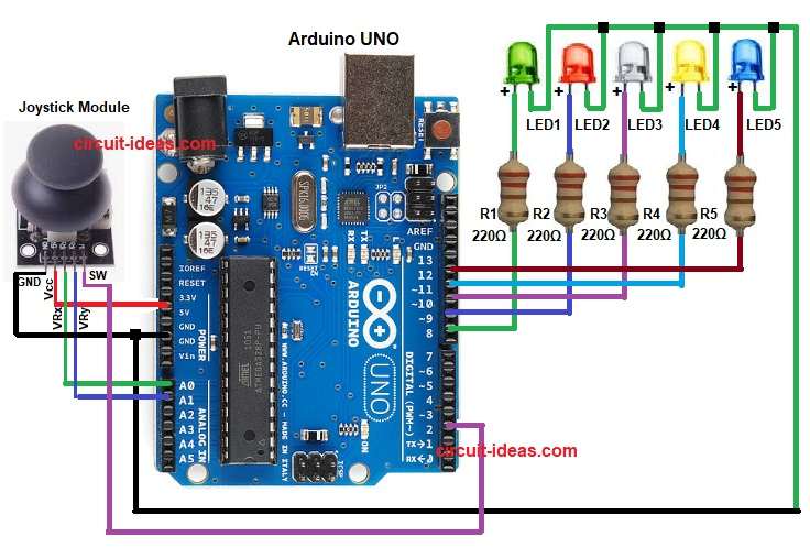
Parts List:
| Components | Quantity |
|---|---|
| Resistors 220Ω 1/4 watt | 5 |
| Arduino UNO | 1 |
| Joystick Module | 1 |
| LEDs 5mm any | 5 |
| USB Cable | 1 |
To begin with, the joystick has two potentiometers inside, one for X direction and one for Y direction.
When we move the stick, the voltage changes and then Arduino reads this voltage on A0 and A1 pins; according to movement, Arduino turns different LEDs ON.
When joystick goes up, one LED glows and when joystick goes down, other LED glows; also right and left also glow different LEDs and center position means no LED or one LED.
How to Build:
To build a Arduino and Joystick LED Controller Circuit following are the steps we need to follow:
- First, gather all the parts as shown in circuit diagram.
- Next, Joystick VRx pin goes to Arduino A0 and Joystick VRy pin goes to Arduino A1.
- Then Joystick SW pin goes to Arduino D2, Joystick VCC pin goes to Arduino 5V and Joystick GND pin goes to Arduino GND.
- Then LED 1 anode goes to pin 8 through 220 ohm resistor R1 and LED 2 anode goes to pin 9 through 220 ohm resistor R2.
- After that, LED 3 anode goes to pin 10 through 220 ohm resistor R3 and LED 4 anode goes to pin 11 through 220 ohm resistor R4.
- Now LED 5 anode goes to pin 12 through 220 ohm resistor R5.
- Finally, all LED cathodes go to GND.
Conclusion:
To conclude, this project is easy as it teaches how to read joystick values and control LEDs, also it is good for learning analog input.
We can also use this idea for robot control and gaming projects, furthermore, this Arduino and Joystick LED Controller Circuit uses low cost components and offers a simple and fun design.