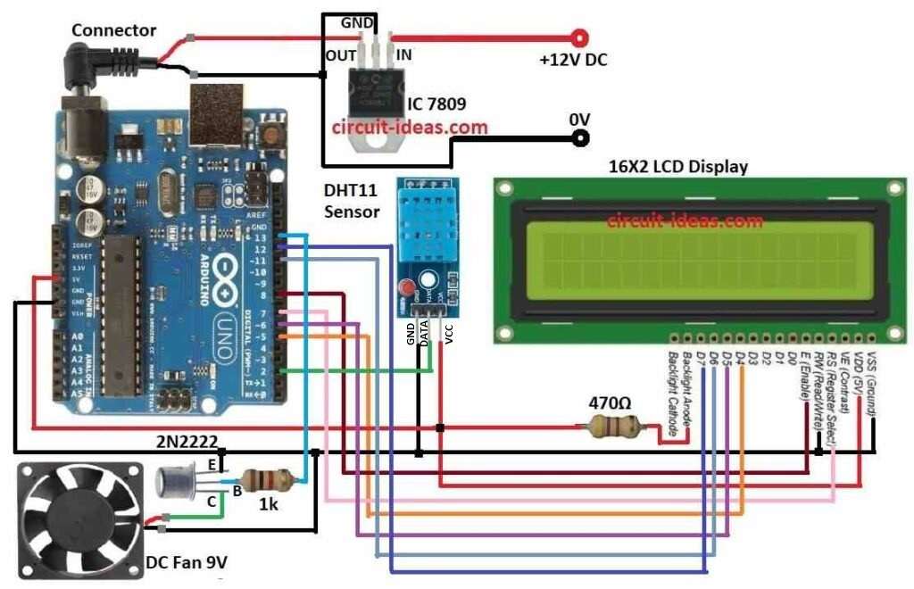
This article show how to make Arduino Temperature Controller Circuit using DC Fan Arduino UNO, LCD, transistor, DHT11 sensor and with few resistors.
It show temperature and fan speed on LCD and control fan speed based on room temperature in home or office.
Fan turns ON and OFF automatic when temperature goes above or below a set limit.
Coding:
#include <LiquidCrystal.h>
#include <DHT.h>

#define DHTPIN 2     // Digital pin connected to DHT sensor
#define DHTTYPE DHT11 // DHT sensor type

#define FANPIN 3     // Digital pin connected to transistor base

#define LCD_RS 7     // LCD Register Select pin
#define LCD_EN  8     // LCD Enable pin
#define LCD_D4  5     // LCD Data pin 4
#define LCD_D5  6     // LCD Data pin 5
#define LCD_D6  11    // LCD Data pin 6
#define LCD_D7  12    // LCD Data pin 7

#define TEMP_THRESHOLD 25.0 // Temperature threshold in degrees Celsius

LiquidCrystal lcd(LCD_RS, LCD_EN, LCD_D4, LCD_D5, LCD_D6, LCD_D7);
DHT dht(DHTPIN, DHTTYPE);

void setup() {
  lcd.begin(16, 2);
  dht.begin();
  pinMode(FANPIN, OUTPUT);
}

void loop() {
  float temperature = dht.readTemperature();
  float humidity = dht.readHumidity();

  if (isnan(temperature) || isnan(humidity))
 {
    lcd.setCursor(0, 0);
    lcd.print("Error reading DHT sensor!");
  } else {
    lcd.setCursor(0, 0);
    lcd.print("Temp: ");
    lcd.print(temperature);
    lcd.print(" C  Humidity: ");
    lcd.print(humidity);
    lcd.print("%");

    if (temperature >= TEMP_THRESHOLD) {
      digitalWrite(FANPIN, HIGH);
    } else {
      digitalWrite(FANPIN, LOW);
    }
  }

  delay(1000);
}
Code Explanation:
- DHT11 sensor read room temperature and humidity.
- LCD show current temperature and humidity.
- Transistor control DC fan using temperature.
- Fan turns ON when temperature cross set limit (threshold).
Code Logic:
- Read temperature and humidity using DHT11.
- Check if sensor reading is correct.
- Show values on LCD.
- Compare temperature with threshold.
- If hot then fan turns ON and If not fan turns OFF.
Circuit Working:
Parts List:
| Component | Quantity |
|---|---|
| Resistor | |
| 1k 1/4 watt | 1 |
| 470Ω 1/4 watt | 1 |
| Semiconductors | |
| Arduino UNO | 1 |
| DHT11 sensor | 1 |
| DC Fan 9V | 1 |
| 16×2 LCD | 1 |
| IC 7809 | 1 |
| Transistor 2N2222 | 1 |
This circuit project is easy to work and make.
Arduino make PWM at PWM pin and sends to transistor base.
Transistor give voltage based on PWM signal.
PWM control fan speed through transistor.
DHT11 send temperature and humidity to Arduino.
Arduino check if temperature is more than set limit.
If temperature is high then transistor turns ON and fan starts.
If temperature is low then transistor turns OFF and fan stops.
LCD shows current temperature and humidity.
How to Build:
To build a Arduino Temperature Controller Circuit using DC Fan following are the steps for connections:
- Collect all parts from circuit diagram.
- Use IC 7809 to give 9V regulated power to Arduino.
- Connect 470Ω resistor from LCD backlight anode to Arduino 5V.
DC Fan Connection:
- Fan (+) wire goes to collector of 2N2222 transistor.
- Fan (–) wire goes to GND.
Transistor 2N2222 Connection:
- Connect collector to fan (+) wire.
- Connect base to Arduino pin 13 through 1k resistor.
- And connect emitter to GND.
DHT11 Sensor Connection:
- Connect VCC to Arduino 5V.
- Connect GND to Arduino GND.
- Connect DATA to Arduino pin 2.
LCD Connection to Arduino:
- Connect VDD to Arduino 5V.
- Connect VSS (GND) to Arduino GND.
- Connect D4 to Arduino pin 5.
- Connect D5 to Arduino pin 6.
- Connect D6 to Arduino pin 11.
- Connect D7 to Arduino pin 12.
- Connect RS to Arduino pin 7.
- Connect Enable to Arduino pin 8.
- Connect R/W to Arduino GND.
Conclusion:
This Arduino Temperature Controller Circuit control DC fan based on room temperature.
Its threshold temperature can be changed.
If we require more features like humidity and alerts it can be added.
References:
Trouble turning on temperature controlled DC fan at the correct value