Simple 12V DC Fan Speed Controller Circuit is an useful project in electronics, it changes fan speed by adjusting the voltage; also, this post talks about fan speed controller using IC LM2941.
LM2941 is low dropout voltage regulator and it handles up to 1A current and it is good for cooling, temperature control and automation projects.
Further, in this article we will see how circuit works using LM2941 as adjustable voltage regulator.
Circuit Working:
Parts List:
| Components | Values | Quantity |
|---|---|---|
| Resistors | 2.2k 1/4 Watt | 1 |
| Potentiometer 22k, 10k | 1 each | |
| Capacitors | Ceramic 470nF | 1 |
| Electrolytic 470µF 25V | 1 | |
| Semiconductors | IC LM2941 | 1 |
| 12V DC Fan | 1 |
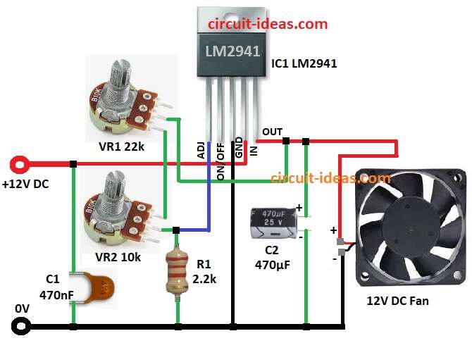
This diagram shows how fan speed controller works with IC LM2941 and t his LM2941 is voltage regulator and it adjusts output voltage.
Potentiometers VR1, VR2 and resistor R1 make voltage divider and this sets fan speed., also circuit uses 12V DC input.
Then capacitor C1 keeps input voltage stable and LM2941 controls output voltage using resistors in feedback loop.
After that, we can get output voltage at one pin using formula and capacitor C2 smooths output voltage and gives steady power to fan.
Finally, fan runs good and speed changes by adjusting the resistors.
Formulas:
Here is formula with example for 12V DC fan speed controller:
Output Voltage Formula:
Vout = Vref × (1 + (VR1 / VR2)) + (Iadj × R1)
where,
- Vref is the 1.275V for IC LM2941
- Iadj is very small so we can skip it
How to Build:
To build a Simple 12V DC Fan Speed Controller Circuit follow below steps for connections of the circuit:
- First, put all parts as shown in circuit diagram.
- Next, connect one end of VR1 to OUTPUT pin and other end to VR2, VR2 other end goes to one side of R1 and other side of R1 to GND.
- Then ADJ pin 1 of IC1 connects between VR2 and R1 and GND pin 3 of IC1 goes to GND and also INPUT pin 4 connects to +12V DC.
- Also, one side of C1 goes to INPUT pin and other side to GND.
- After that, positive side of C2 goes to OUTPUT pin 5 and negative goes to GND.
- Lastly, connect fan positive to OUTPUT pin 5 and negative to GND.
Conclusion:
To conclude, Simple 12V DC Fan Speed Controller Circuit using IC LM2941 is easy and with low cost., as this circuit needs only few parts.
Also, it gives stable and adjustable fan speed and if required change resistor values to control fan speed.
Hence, this circuit is good for cooling, automation and other projects.
Leave a Reply