Digitally Controlled Adjustable Voltage Regulator Circuit provides an adjustable output voltage for different applications; also the popular LM317 regulator IC delivers an adjustable output voltage ranging from 1.25V to 37V.
Furthermore, in this circuit LM317 IC work with digital control transistors and let user choose voltage easy; it is also good for different voltage need like microcontroller, power supply and for test tools.
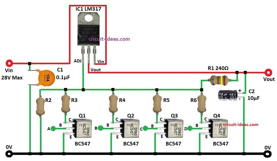
Circuit Working:
Parts List:
| Components | Values | Quantity |
|---|---|---|
| Resistor | 240Ω 1/4 watt | 1 |
| Capacitors | Ceramic 0.1µF | 1 |
| Electrolytic 10µF | 1 | |
| Semiconductors | IC LM317 | 1 |
| Transistor BC547 | 4 |
IC LM317 is a special three-terminal device that maintains a steady 1.25V between the output and adjust pins.
Resistors connected between the output, adjust pin, and ground set the desired output voltage.
Here resistors R2, R3, R4, R5, R6 make different voltage levels and transistors Q1, Q2, Q3, Q4 act like switches.
Also, when transistor is ON it connect resistor to circuit and change output voltage.
Output voltage formula for R2 to R6 is:
V_out = 1.25V × (1 + (R_set / R3)) + I_adj × R_set
Formulas with Calculations:
Formulas for Digital Adjustable Voltage Regulator:
V_out = 1.25V × (1 + (R_set / R3)) + I_adj × R_set
here,
- R_set is the resistor from R2, R3, R4, R5, or R6
- R3 is the fixed 240Ω resistor
- I_adj is the small current
So,
V_out = 1.25V × (1 + (R_set / 240Ω))
Example: If R_set = 1kΩ,
V_out = 1.25V × (1 + 1000/240) = 6.46V
Therefore, different R_set gives different output voltage.
How to Build:
To build a Digitally Controlled Adjustable Voltage Regulator Circuit follow the below mentioned steps:
- First, put all parts as circuit show.
- Next, connect IC1 ADJ pin 1 to resistor divider between R5 and R6.
- After that, connect IC1 OUTPUT pin 2 to Vout regulated voltage.
- Now connect IC1 INPUT pin 3 to Vin input voltage.
- Also, connect Q1 to Q4 collector pins to resistors R3 to R6 as per formula, connect Q1 to Q4 base to digital control inputs A, B, C, D and then connect Q1 to Q4 emitter to ground.
- Further, connect resistor R2 from junction of R3 and ground.
- Then connect resistor R1 between OUTPUT pin 2 and resistor R6.
- Connect capacitor C1 from INPUT pin 3 to ground and then connect capacitor C2 positive to OUTPUT pin 2 and negative to ground.
Conclusion:
To conclude, this Digitally Controlled Adjustable Voltage Regulator Circuit uses IC LM317 to work good and also user can select output voltage by turning ON the transistors.
Moreover, this circuit is good for projects need different voltages like embedded system, test tools and for DIY power supply.