
In many electronic projects, we need a higher DC voltage, but sometimes transformer gives low AC voltage; for example, a 9V AC transformer is common, therefore, we use voltage doubler circuit and this increases voltage without using high voltage transformer.
Besides increasing the voltage, this circuit also converts AC into DC and also there are two types of voltage doubler circuit:
- First is Half Wave Voltage Doubler.
- Second is Full Wave Voltage Doubler.
Both circuits use diodes and capacitors, so let us understand working of both this circuit in simple way.
Circuit Working for Half Wave Voltage Doubler:
Parts List:
| Components | Values | Quantity |
|---|---|---|
| Capacitors | Electrolytic 470uF 50V | 2 |
| Semiconductors | Rectifier Diodes 1N4007 | 2 |
| Transformer 220V AC Primary to 9V AC Secondary | 1 | |
| Input Supply 220V AC 50Hz | 1 | |
| Output Voltage approximately 25V DC | 1 |
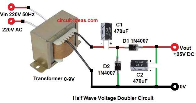
First, the 220V AC supply powers the transformers primary winding; the transformer then steps the voltage down to 9 V AC.
Then, during the positive half-cycle, diode D1 conducts and charges capacitor C1 to the peak voltage. For a 9 V AC input, the peak voltage is approximately 12.7 V.
During negative half cycle the D1 blocks and D2 conducts and now C1 voltage adds with AC voltage and then capacitor C2 charges to nearly double voltage.
As a result, output becomes around 25V DC with no load but however, under load voltage becomes little less.
How to Build Half Wave Voltage Doubler Circuit:
To build a Half Wave Voltage Doubler Circuit follow the below connection steps:
- First, gather all the circuit parts as in circuit diagram.
- Next, transformer primary side one end connect to 220V phase and other end connect to 220V 0V and from transformer secondary one pin connect capacitor C1 negative.
- Then capacitor C1 positive connect to junction of diode D1 anode and D2 cathode.
- After that, capacitor C2 positive connect between diode D1 cathode and output positive and capacitor C2 negative connect to 0V.
- Now connect diode D2 cathode between capacitor C1 positive and diode D1 anode.
Circuit Working for Full Wave Voltage Doubler:
Parts List:
| Components | Values | Quantity |
|---|---|---|
| Capacitors | Electrolytic 470uF 50V | 2 |
| Semiconductors | Rectifier Diodes 1N4007 | 2 |
| Transformer 220V AC Primary to 9V AC Secondary | 1 | |
| Input Supply 220V AC 50Hz | 1 | |
| Output Voltage approximately 25V DC | 1 |
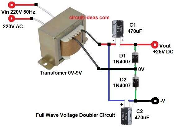
For full wave voltage doubler again transformer gives 9V AC output.
During positive half cycle the upper diode conducts and upper capacitor charges and during negative half cycle the lower diode conducts and lower capacitor charges.
After that, both capacitor voltages add in series and therefore, output becomes nearly double peak voltage and therefore, full wave circuit is better, because ripple is less and its efficiency is more.
How to Build Full Wave Voltage Doubler Circuit:
To build a Full Wave Voltage Doubler Circuit follow the below connection steps:
- First, gather all the parts as per circuit diagram.
- Next, transformer primary one end connect to 220V phase and other end of primary connect to 220V 0V.
- Then transformer secondary one end connect to capacitor C1 negative and positive of capacitor C1 goes to Vout 25V.
- Further, secondary other end connect between diodes D1 and D2.
- Also, connect diode D1 between capacitor C1 positive and Vout 25V and connect diode D2 in series with diode D1.
- Now connect capacitor C2 positive of negative of capacitor C1 and negative of capacitor C2 connect to -V supply.
Formula with Calculation:
First let us calculate peak voltage.
Vrms = 9V
Peak voltage formula:
Vpeak = Vrms × 1.414
= 9 × 1.414
Vpeak = 12.726V
Now voltage doubler output:
Vout = 2 × Vpeak
= 2 × 12.726
Vout = 25.45V
Now subtract diode drop.
Each diode drop = 0.7V
Approx DC output:
Vout = 25.45 − 1.4
Vout = 24V to 25V
Therefore, under load it may drop to 22V to 24V.
Conclusion:
To conclude, the Half-Wave and Full-Wave Voltage Doubler Circuit offers a simple and useful design that converts 9V AC into nearly 25V DC.
However, it provides only limited output current, making it suitable for low-current applications.
Half wave circuit is simple but ripple is more and full wave circuit is better because ripple is less and performance is stable, so if we want better output then choose full wave type.
Finally, always use correct capacitor voltage rating and always check diode direction before power ON.