In this post we will understand How to Increase 7805 Output Voltage using Diodes.
Normally, L7805 gives fixed 5V output, but by adding diode in ground line, we can increase output voltage little bit.
This method is simple and is with low cost, as it is useful when we need slightly higher voltage like 5.7V or 6.4V without using adjustable regulator.
Circuit Working:
Parts List:
| Components | Values | Quantity |
|---|---|---|
| Capacitors | Ceramic 0.1µF | 3 |
| Semiconductors | IC 7805 Voltage Regulator | 1 |
| Diodes 1N4007 | 3 | |
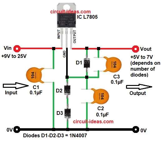
| Input supply (Vin) is from 9V to 25V DC and Output voltage (Vout) approx 5V to 7V using 2 diodes | 1 |
In normal condition, IC 7805 gives 5V between output pin and ground pin, but in this circuit we do not connect ground pin directly to real ground, but connect diodes between ground pin and actual ground.
Each diode creates voltage drop around 0.7V, because of this drop, regulator ground pin lifts above real ground and so output voltage also increases.
Example:
If one diode used then output becomes about 5V + 0.7V = 5.7V
If two diode used then output becomes about 5V + 1.4V = 6.4V
Capacitors are used for filtering, they reduce noise and keep voltage stable.
Formulas with Calculations:
Output voltage formula:
Vout = 5V + (number of diodes × 0.7V)
Calculation Example:
For 2 diodes:
Vout = 5 + (2 × 0.7)
Vout = 5 + 1.4
Vout = 6.4V
For 3 diodes:
Vout = 5 + (3 × 0.7)
Vout = 5 + 2.1
Vout = 7.1V
Note: Actual diode drop may change from 0.6V to 0.8V depending current and temperature.
How to Build:
How to Increase 7805 Output Voltage using Diodes follow the below connection steps:
- First, the circuit starts by collecting all its components as shown in circuit diagram above.
- Then stat with IC pin Input which connect to input voltage between 9V to 25V and add capacitor C1 between input and ground.
- Then IC ground pin do not connect directly to ground, connect series diodes D2, D3 between this pin and actual ground, as these step increases output voltage.
- Then the last pin output, take output from this pin.
- Protection diode D1 connect between output and ground pin of IC to protect regulator from reverse current.
- Capacitor C2 connect between ground pin of IC and actual ground to reduce ripple.
Conclusion:
This circuit for How to Increase 7805 Output Voltage using Diodes gives simple way to increase voltage of IC L7805, as it uses diode drop method and it does not need any complex components, but output voltage is not very accurate.
Temperature and load current can change voltage, we can use this method for simple projects only, for precise voltage control we need to use adjustable regulator like LM317.
Leave a Reply