NOT gate also name as inverter, it changes from 1 to 0 and 0 to 1 and we can also make Logic NOT gate circuit with one transistor.
This is very simple and work with digital signal and it uses very less parts; moreover, output is opposite of input and it works fast and it is useful in digital circuit, computer, electronic project.
Also, this project is easy to learn and can be built at home, it can also be used for logic operations and signal control.
Truth Table for Logic NOT Gate:
The truth table below represents the operation of a NOT gate:
| Input (A) | Output (Y) |
|---|---|
| 0 | 1 |
| 1 | 0 |
The above table shows: NOT gate give opposite output, when input 0 then output 1 and when input is 1 then output 0; then it always invert the signal
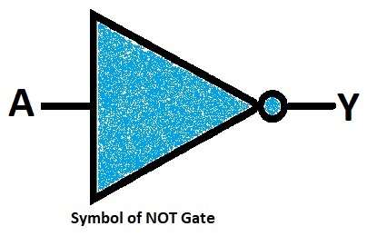
Symbol of Logic NOT Gate:
Circuit Working:
Parts List:
| Components | Quantity |
|---|---|
| Resistors | |
| 1k | 1 |
| 10k | 2 |
| Semiconductors | |
| Transistor BC547 | 1 |
| LED | 2 |
| Power supply 5V | 1 |
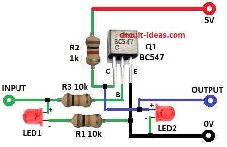
Above circuit diagram uses NPN transistor and input go to transistor base through resistor R3.
Also, if input is HIGH to 5V then transistor is ON, then output become LOW to 0V and if input is LOW to 0V then transistor is OFF.
Then output become HIGH to 5V and LED show output state.
How to Build:
To build a Logic NOT Gate Circuit with Transistor follow the below steps:
- First, take all the parts as shown in circuit diagram.
- Next, transistor base connects via resistor R3 to input, transistor collector connects via R2 to +5V power supply and transistor emitter connect to ground of the circuit.
- Then connect resistor R1 between the junction of emitter, Gnd and cathode of LED1 and anode of LED1 goes to INPUT
- After that, connect anode of LED2 between collector of transistor and resistor R2 and cathode of LED2 connect to GND
Conclusion:
To conclude, this transistor-based logic NOT gate circuit is simple and easy to build, and it can invert signals in logic circuits; also, LED shows output state and it is good for learning basic digital electronics.