John W. Ecklins patent show special generator.
It give more power out than it take in.
In this post there are Two Ways to Make Free Energy: John Ecklins Smart Design:
First way: small motor spin magnetic shield and make changing magnetic field and powers generator.
Second way: shield move back and forth and make spinning motion and turn many generators.
Ecklin Brown Generator is similar.
It spin shield to block magnetic force and make direct electric power.
Making this at home is hard and is very complex.
But idea can help.
We can try small changes by using straight bar cores and normal parts.
Exploring Ecklins Patent for Efficient Magnet/Electric Motor Generators:
On March 29 1974 John W. Ecklin get US Patent No. 3,879,622.
It is for new magnet/electric motor generator.
People say it give more power out than power in to run.
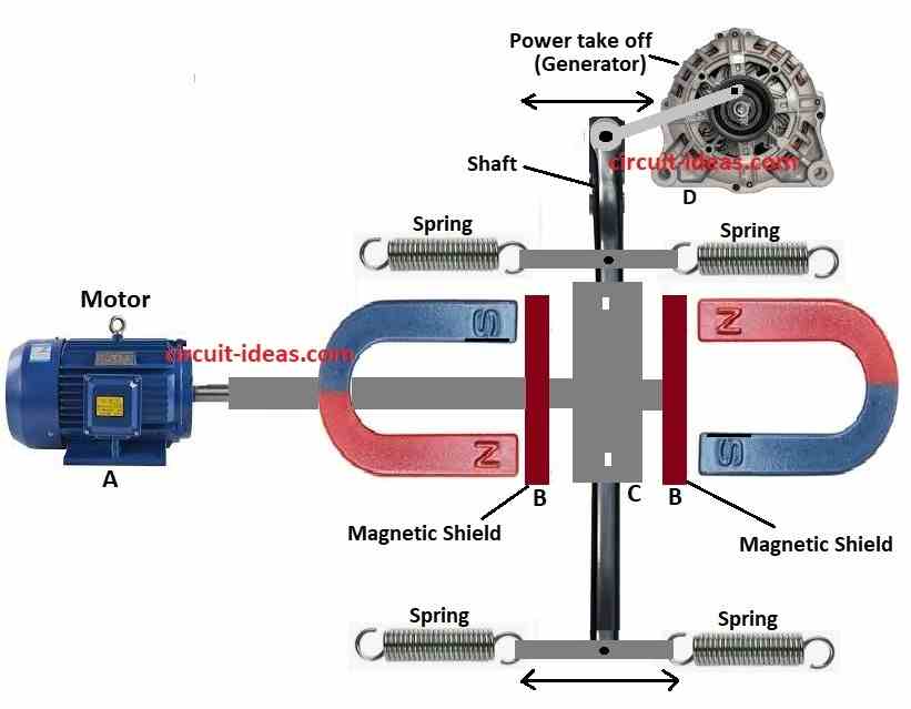
Patent tell us two ways to use this system.
First way:
Small motor spin magnetic shield.
Shield block pull between two magnets.
This make changing magnetic field and through that powers the generator.
Diagram show motor at point ‘A’ spin shaft and shield strips at point ‘B’.
Shield made of mu-metal.
When lined up with magnet ends it make strong path for magnetic force and stops magnet pull at point ‘C’.
Now when left magnet open and right one is blocked and spring-loaded part which is the traveler moves left.
When right magnet open and left blocked then traveler move right and motor shaft keep turning.
This back and forth oscillation goes to point ‘D’ through mechanical link and turn shaft to run the generator.
System said to give more power out than in.
Shield spin is easy and maybe enough to power motor too.
Second way:
Still use shield but in other style.
Shield make back and forth motion.
That motion turn into spinning power two generators.
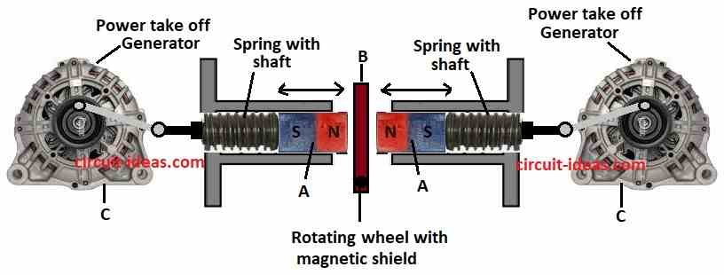
Two magnets marked ‘A’ held together by springs.
Springs stretch just enough to go through magnetic shield ‘B’.
Small motor move the shield.
This make magnets push against each other with North pole to North pole.
When magnets pushes springs compress and this move links at point ‘C’.
Links turn two shafts and through this shafts make power.
Ecklin Brown Generator is similar but it make direct electric output which is not just mechanical motion.
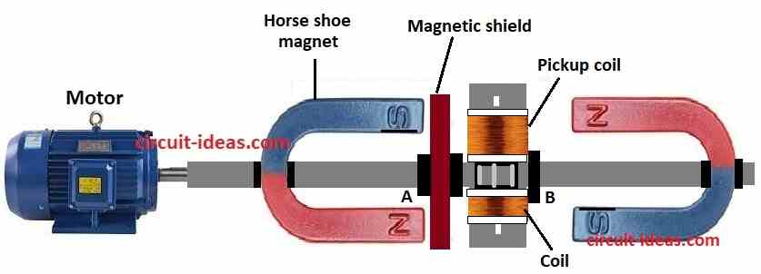
Same motor and spinning shield used in this version too.
But now pickup coils are wrapped around center I-shaped piece made of thin iron layers.
This iron I-piece stop magnetic force from passing through.

When device is working magnetic lines go through pickup coils and move down.
As motor shaft turn 90 degrees more then magnetic lines move higher in coils.
Each full turn of shaft makes four times magnetic change with flux reversal.
Instead of electric motor we can use permanent magnet motor to spin mu-metal shield in Ecklin Brown system.
Many free energy devices have round toroid shape which is important.
For home use can make smaller version using straight bar cores.
Use soft iron or masonry anchors for core.
But need to cut off conical end of anchor so it makes magnet power worse.

This way we can wrap coil in spiral shape on shaft or on bobbin that fits over shaft.
Easy to do using hacksaw and vise.
Thicker wire gives more current without heat.
More turns of coil give more voltage.

Strong magnetic field made by magnets at both ends of core are going through coil.
As motor turns screening arms switch between magnets.
This makes changing magnetic field in coil.
Can also use 2, 3 or 4 output coils all designs are possible.
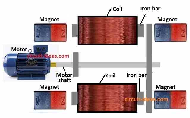
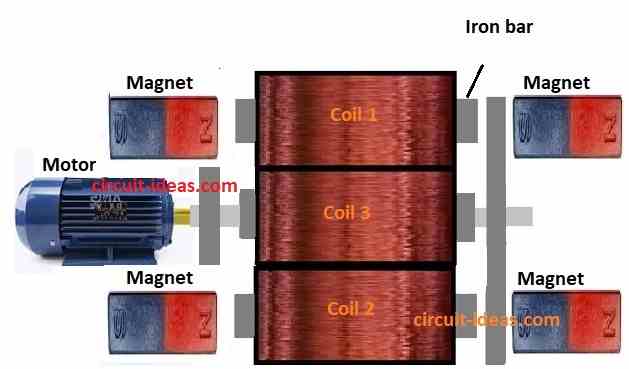
Coils can connect in series to get more voltage or in parallel to get more current.
In design the shields are on motor shaft.
But better design are possible.
Use separate axle with belt and pulley.
This help with better coil and magnet placement.
This design can be more hard but will work better.
Conclusion:
To end Two Ways to Make Free Energy: John Ecklins Smart Design show new way for magnet/electric motor generator.
It give more power out than power in.
Device uses small motor to spin magnetic shield and this make changing magnetic field that runs generator.
Another design uses back and forth (reciprocating) motion to make two spinning outputs.
Ecklin Brown Generator is similar but give direct electric power with spinning shield.
Making full device is hard for DIY people but basic ideas can be used in simple working designs.
Ecklins invention still show big promise today.
Leave a Reply