
This project is for LED Binary Counter Circuit, which uses IC 555 timer as clock pulse generator and it also uses 74HC4040 binary counter IC.
The LEDs connect to the outputs to display the binary count and the circuit operates from a 6 V battery or a DC power supply.
Circuit Working:
Parts List:
| Components | Values | Quantity |
|---|---|---|
| Resistors | 1k | 2 |
| 10k | 1 | |
| 220Ω | 1 | |
| Capacitors | Electrolytic 47µF 25V | 1 |
| Ceramic 0.01µF | 1 | |
| Semiconductors | IC 555 Timer | 1 |
| IC HD74HC4040 Binary Counter | 1 | |
| LEDs 5mm 20mA any color | 9 | |
| Battery 6V DC Supply | 1 |
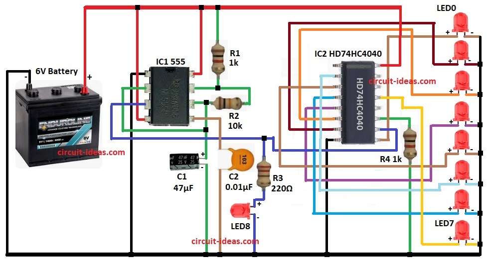
The circuit uses a 6V battery or regulated DC supply and IC1 555 is in astable mode, generating continuous clock pulses.
Also, R1, R2 and C1 set the pulse frequency and each pulse goes to the clock input of IC2 74HC4040.
Then IC2 is a 12-stage binary ripple counter and each pulse increments the binary count.
After that Outputs Q0 to Q7 light up LEDs and then LEDs display the binary value.
C2 filters noise in the circuit, R3 limits current to the LEDs and then R4 connects to the reset pin (MR).
Finally, when MR is high then the counter resets to zero.
Formulas:
Formula for 555 Astable Frequency:
f = 1.44 / ((R1 + 2R2) × C1)
here,
- f is the output frequency of the 555 timer (Hz)
- R1 and R2 are the resistors controlling timing
- C1 is the capacitor controlling timing
How to Build:
To build a LED Binary Counter Circuit follow the below steps for connections:
- First, take all the components as shown in circuit diagram
Connection of IC1 555:
- Next, IC 555 pin 1 to ground.
- Then pin 2 and pin 6 shorted.
- After that, pin 3 output clock pin connected to pin 10 of IC2
- Also, pin 4 reset go to +6V.
- Further, pin 7 DC pin goes between resistors R1 and R2.
- Now pin 8 Vcc pin go to +6V.
- Pin 2 of IC1connects to junction of R2 and C1 and pin 5 connected to capacitor C2 to ground.
Connections of IC2 74HC4040:
- Next, outputs pins of IC2 are pins 9, 7, 6, 5, 3, 2, 4, 13.
- Additionally, each output pin connects to the anode of LEDs 1 to 8, while the cathodes of the LEDs connected to ground.
- Now pin 8 go to ground.
- The IC 555 output drives pin 10 (the clock input) through resistor R3 and LED9, while resistor R4 connects pin 11 (the MR reset pin) to ground.
Connection of battery 6V:
- Also, 6V battery positive side connects to the positive terminal of the circuit and 6V battery negative side connects to the GND of the circuit
Conclusion:
To conclude, this LED Binary Counter Circuit is simple to make, as IC1 555 makes clock pulses and IC2 74HC4040 counts pulses.
Also, LEDs show binary numbers, furthermore, circuit is useful for students and beginners and it teaches binary counting and digital IC use.