Flex sensor is a small strip that changes resistance when we bend it.
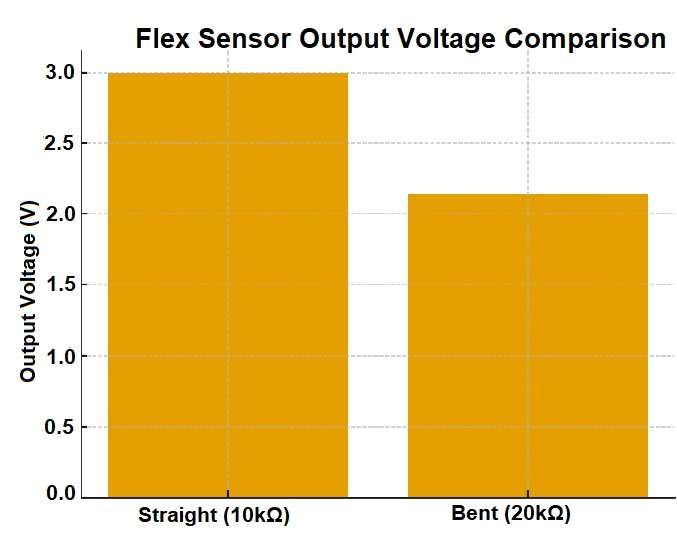
When the sensor remains straight, it has low resistance and when it bends, its resistance increases; also many robots, gloves, gaming devices, medical tools, wearables, and other projects use this sensor.
Additionally, sensor works simple, as with more bend it gives more resistance.
Flex Sensor Output Voltage Comparison Graph:
Circuit Working:
Parts List:
| Components | Quantity |
|---|---|
| Resistor 15k 1/4 watt | 1 |
| Flex Sensor | 1 |
| Multimeter | 1 |
Flex sensor is like a resistor, when we bend it, the material stretches and its resistance goes up.
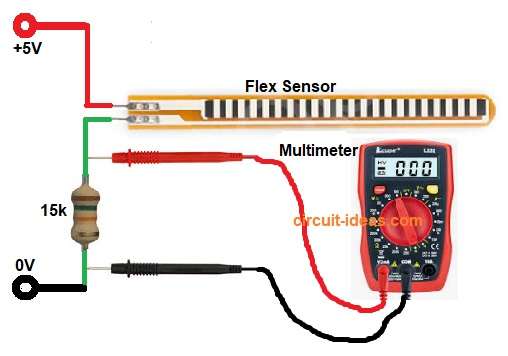
Microcontroller cannot read resistance directly, so we use a voltage divider; also flex sensor and a fixed resistor make a divider and the divider gives changing voltage when sensor bends.
Finally, this voltage is easy to read by Arduino or meter.
How to Build:
For Measuring Bend Angle using a Flex Sensor Circuit follow the below steps:
- First, take all the parts as shown in circuit diagram.
- Next, flex sensor pin 1 goes to 5V and flex sensor pin 2 joins with one side of 15k resistor and other side of resistor goes to ground.
- Also, the join point gives output voltage and this output goes to multimeter positive or Arduino analog pin.
- Then ground of meter or Arduino goes to ground.
Conclusion:
To conclude, Flex sensor is simple to use and when it bends, resistance changes; also with a voltage divider, we get a changing voltage.
Therefore, this voltage shows how much bend happens, as this project is cheap and very common in motion and gesture projects and is also good for beginners and useful in many electronics ideas.

Leave a Reply