If we want Arduino to feel the movement, flex sensor is best; with no click, no sound only smooth bending, also it bends and Arduino gets new value every time.
Perfect for beginners who want to control things by bending and further its a simple circuit, with simple code, powerful idea.
Arduino Code:
int flex = A0;
int led1 = 4;
int led2 = 5;
int value = 0;

void setup() {
pinMode(led1, OUTPUT);
pinMode(led2, OUTPUT);
Serial.begin(9600);
}

void loop() {
value = analogRead(flex);
Serial.println(value);

if(value > 600) {
digitalWrite(led1, HIGH);
digitalWrite(led2, LOW);
} else {
digitalWrite(led1, LOW);
digitalWrite(led2, HIGH);
}
delay(100);
}
Code Explanation:
- First we set flex sensor pin as analog input.
- Two LEDs set as outputs.
- Inside loop we read sensor value.
- Serial monitor prints value.
- If value high means more bend.
- Then LED is on pin 4 turns ON.
- LED on pin 5 turns OFF.
- If value low means less bend.
- Then LED on pin 4 turns OFF.
- LED on pin 5 turns ON.
- Simple if else logic.
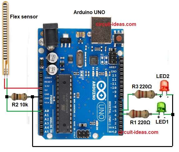
Circuit Working:
Parts List:
| Components | Quantity |
|---|---|
| Resistors | |
| 220Ω | 2 |
| 10k | 1 |
| Semiconductors | |
| Arduino UNO | 1 |
| Flex sensor Module | 1 |
| LED Blue 5mm | 1 |
| LED Green 5mm | 1 |
| USB Cable | 1 |
First, power comes from Arduino 5V and then flex sensor connects between 5V and analog pin A0.
A 10k resistor connects from A0 to GND and this makes voltage divider and then flex sensor acts like changing resistor.
Moreover, when straight, resistance is low and when bent then resistance is high; because resistance changes then voltage at A0 also changes.
Arduino then reads this voltage as analog value 0 to 1023.
Also, if sensor bends more, then voltage becomes lower and if sensor bends less, then voltage becomes higher and Arduino checks this value again and again in loop.
Further, if value crosses set limit then Arduino turns one LED ON and other LED turns OFF and finally, if value goes below limit then Arduino switches LEDs again.
Formula:
Below is the voltage divider formula:
Vout = Vin * R10k / (Rflex + R10k)
where,
- Vout is the output voltage of voltage divider.
- Vin is 5V.
- Rflex is flex sensor resistance.
- R10k the 10k ohm fixed resistor.
How to Build:
To build a Arduino Flex Sensor Circuit follow the below steps for connection:
- First, gather all the parts as shown in circuit diagram.
- Next, flex sensor has two pins, one pin goes to 5V and other pin goes to analog pin A0.
- Then a 10k resistor goes from A0 to GND.
- The circuit also connects two LEDs, the green LED connects to digital pin 4 through a 220 ohm resistor, and the blue LED connects to digital pin 5 through a 220 ohm resistor.
- Now GND from Arduino connects to all negative LED pins and bottom of 10k resistor.
Conclusion:
Overall, Flex sensor gives easy way to measure bend, Arduino reads change and controls output and also, Arduino Flex Sensor Circuit is simple and uses voltage divider.
Finally, circuit is useful in glove projects, robotics, gesture control and DIY experiments and is also easy for beginners.

Leave a Reply