A rotary encoder is a sensor that detects rotation and direction; also people use it in volume knobs, motors, robot wheels and menu selection systems.
Arduino can read the encoder pulses and show value in serial monitor; further this project for KY040 Encoder Module Circuit with Arduino is very simple and beginner friendly.
Arduino Code:
int clk = 6;
int dt = 7;
int counter = 0;
int lastState;

void setup() {
Serial.begin(9600);
pinMode(clk, INPUT);
pinMode(dt, INPUT);
lastState = digitalRead(clk);
}

void loop() {
int currentState = digitalRead(clk);
if (currentState != lastState) {
if (digitalRead(dt) != currentState) {
counter++;
} else {
counter--;
}
Serial.println(counter);
}
lastState = currentState;
}
Coding Explanation:
- clk pin gives pulse when turning.
- dt pin tells direction.
- Arduino store last state.
- If state changes then rotation happen.
- If dt is different from clk then clockwise.
- If dt same then anticlockwise.
- Counter increase or decrease.
- Serial monitor show value.
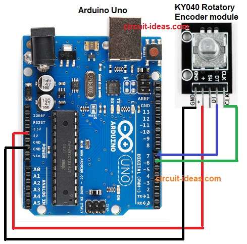
Circuit Working:
Parts List:
| Components | Quantity |
|---|---|
| Arduino Uno | 1 |
| KY040 Rotatory Encoder module | 1 |
| USB cable | 1 |
Power goes from USB to Arduino and then Arduino gives 5V and GND to the rotary encoder; then encoder knob turns and makes two pulse signals on CLK and DT pins.
Furthermore, Arduino reads change on CLK and at that moment Arduino checks DT.
If DT is different from CLK clockwise and if DT is same as CLK anticlockwise, then Arduino increases or decreases counter value.
Finally, serial monitor shows the new counter value and this is how the circuit reads rotation and direction.
Formula with Calculation:
Basic formula:
angle = steps × stepAngle
where,
- angle is the total rotation amount.
- steps means how many pulses the encoder counted
- stepAngle means degrees per one step (example: 18° per step)
So when knob turns Arduino counts steps, then multiply steps by degrees per step and lastly, we get the total rotation angle from starting point.
Example:
steps = 5
stepAngle = 18°
angle = 5 × 18 = 90°
It means the knob rotated 90 degrees.
How to Build:
To build a KY040 Encoder Module Circuit with Arduino follow the below connection steps:
- First, take all the parts as shown in circuit diagram above.
- Next, encoder GND pin goes to Arduino GND, encoder + pin goes to Arduino 5V and encoder CLK pin goes to Arduino pin 6.
- Then encoder DT pin goes to Arduino pin 7 and encoder SW pin, not used in this example.
- Finally, if we want to see numbers on PC, then open serial monitor.
Conclusion:
Overall, the KY040 Encoder Module Circuit with Arduino is simple and requires only two output pins; the code also reads the pulses and displays the count.
Moreover, we can use this for menu, robot wheel, motor position and many projects and is also good for learning digital sensors and interrupts.

Leave a Reply