
This simple Push Button LED Circuit using Arduino shows how to turn an LED ON and OFF using a push button switch.
When we press the button, the LED turns ON, and when you release it, the LED turns OFF; furthermore, this project helps beginners learn about digital input and output in Arduino.
Arduino Coding:
int led = 13;
int button = 2;
int buttonstate = 0;

void setup() {
pinMode(led, OUTPUT);
pinMode(button, INPUT);
}

void loop() {
buttonstate = digitalRead(button);
if (buttonstate == HIGH) {
digitalWrite(led, HIGH);
} else {
digitalWrite(led, LOW);
}
}
Code Explanation:
- Pinmode sets LED as output and button as input.
- Digitalread reads button state.
- The
ifcondition checks whether the button is pressed (HIGH). - if pressed LED turns ON using digitalwrite high.
- Else, LED turns OFF using digitalwrite low.
Circuit Working:
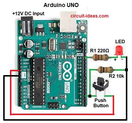
Parts List:
| Components | Values | Quantity |
|---|---|---|
| Resistors | 220Ω 1/4 watt | 1 |
| 10k 1/4 watt | 1 | |
| Semiconductors | Arduino UNO Board | 1 |
| LED 5mm any color | 1 | |
| Push Button Switch | 1 |
When we do not press the button, pin 2 stays LOW and the LED remains OFF; when we press the button, it supplies 5 V to pin 2.
After that, Arduino reads HIGH and LED turns ON and when button released then pin 2 goes LOW again and and LED turns OFF.
Formula:
Below is the formula for Push Button LED Circuit:
Current through LED = V / R = 5V / 220 ohm = 0.022a = 22ma
The circuit uses a 220Ω resistor for the LED, which requires about 20ma of current and additionally, the circuit uses a 10kΩ resistor to keep the input low when no one presses the button.
How to Build:
To build a Push Button LED Circuit using Arduino follow the below steps for connection:
- First, collect all parts same as circuit diagram
- Next, join LED positive leg (anode) to pin 13 using 220 ohm resistor and join LED negative leg (cathode) to ground pin.
- Then connect one side of push button to pin 2 of Arduino and connect other side of push button to 5V pin
- Now put 10k resistor between button pin 2 and ground
Conclusion:
Overall, this project if for Push Button LED Circuit using Arduino, as it shows how to control an led with a push button using Arduino; also circuit is simple and helps to learn digital input and output basics easily