This article shows how to make Simple Battery Eliminator Circuits using 3 Methods with many useful features.
When we need steady DC power for devices then battery eliminator is very useful.
There is no need of normal batteries.
These circuits change AC from transformer to DC power for electronics.
It is very helpful for testing, making new projects or when wall power is better than using batteries.
We see 3 ways to make circuit using diode, capacitor, transformer and more.
Each method use different way to change and clean AC voltage to get steady DC output.
Circuit Working with Formulas:
1. Battery Eliminator Circuit using a Single Diode 1N4007:
Parts List:
| Component | Specification | Quantity |
|---|---|---|
| Capacitor | Electrolytic 1000μF 25V | 1 |
| Diode | 1N4007 | 1 |
| Transformer | 0V-12V 5Amp | 1 |
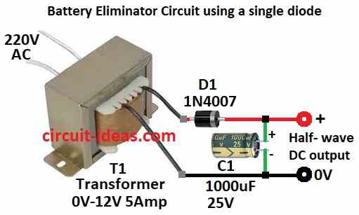
This easy method uses one diode 1N4007 to change AC to DC.
It also uses transformer 0V to12V 5A and capacitor C1 to 1000µF 25V.
Transformer makes high AC voltage to low AC which is good for rectifier.
One diode does half-wave rectification with only half AC pass and gives pulsing DC.
Capacitor smoothers the pulsing DC to more steady DC voltage.
Formulas:
Battery Eliminator with One Diode Half-Wave formula is shown here.
Output DC Voltage:
VDC = VACrms / √2
where,
- VACrms is the AC voltage from transformer RMS value
- VD is the Diode drop to about 0.7V for 1N4007
Ripple Voltage:
Vripple = Iload / (f × C)
where,
- Iload is the load current
- f is the AC frequency from about 50 or 60 Hz
- C is the capacitance for 1000µF
How to Build:
To build a Battery Eliminator Circuit using a Single Diode follow the below mentioned steps for connections:
- Connect one wire from transformer output to diode D1 anode.
- Connect other wire from transformer output to ground 0V.
- Connect D1 cathode to positive side of capacitor C1.
- Connect negative side of C1 to ground 0V.
2. Battery Eliminator Circuit using Two Diodes 1N4007:
Parts List:
| Component | Specification | Quantity |
|---|---|---|
| Capacitor | Electrolytic 1000μF 25V | 1 |
| Diode | 1N4007 | 2 |
| Transformer | 0V-12V 5Amp | 1 |
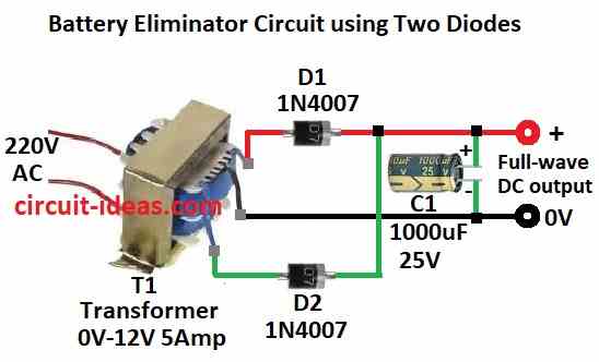
This method uses two diodes for full-wave rectification.
It is better than single diode way.
Transformer still give 0V to 12V AC output.
Two diodes fix both half of AC wave.
This gives higher DC output and less ripple.
Capacitor C1 1000µF 25V still smoothers the output to make steady DC.
Formulas:
Battery Eliminator with Two Diodes for Full-Wave and with center-tap is shown here.
Output DC Voltage:
VDC = VACrms / √2 – VD
where,
- Center tap transformer give two halves each VACrms / 2.
- Need to subtract diode drop VD with 0.7V per diode.
Ripple Voltage:
Vripple = Iload / (2 × f × C)
where,
- Iload is the load current
- f is the AC frequency with 50 or 60 Hz
- C is the capacitance with 1000µF
How to Build:
To build a Battery Eliminator Circuit using Two Diodes follow the below mentioned steps for connections:
- Connect one outer wire from transformer to diode D1 anode.
- Connect center wire from transformer to ground 0V.
- Connect other outer wire from transformer to diode D2 anode.
- Join both D1 and D2 cathodes together.
- Connect joined cathodes to positive side of capacitor C1.
3. Battery Eliminator Circuit using a Bridge Rectifier (4 Diodes 1N4007):
Parts List:
| Component | Specification | Quantity |
|---|---|---|
| Capacitor | Electrolytic 1000μF 25V | 1 |
| Bridge Rectifier | Diode 1N4007 | 4 |
| Transformer | 0V-12V 5Amp | 1 |

This is most advanced method and it uses four diodes 1N4007 to make bridge rectifier.
This way better than other two it changes full AC wave to DC with more stable and efficient way.
Bridge rectifier fix both halves of AC wave and transformer still reduce AC voltage.
Capacitor C1 with 1000µF 25V smooths the DC and give steady output for electronics.
Formulas:
Battery Eliminator with Bridge Rectifier with Full-Wave formula is shown here.
Output DC Voltage:
VDC = VACrms / 2 − 2 × VD
where,
- VACrms is the AC voltage from transformer with RMS value
- VD is the diode drop with 0.7V × 2 = 1.4V total
Ripple Voltage:
Vripple = Iload / (f × C)
where,
- Iload is the load current
- f is the AC frequency from 50 or 60 Hz
- C is the capacitance for 1000µF
How to Build:
To build a Battery Eliminator Circuit using a Bridge Rectifier with with Full-Wave follow the below mentioned steps for connections:
- First make bridge rectifier like in circuit diagram.
- Connect two AC input pins of bridge to transformer secondary wires.
- Connect positive output of bridge to positive side of capacitor C1.
- Connect negative output of bridge to negative side of capacitor C1.
Conclusion:
To conclude, Simple Battery Eliminator Circuits using 3 Methods give steady DC power from AC.
Each method have different level of work and result.
One diode method is very simple but ripple is high.
It uses half-wave rectification.
Two diode method is better and it use full-wave rectification, less ripple and is more efficient.
Bridge rectifier with four diodes is best and it give full-wave DC with low ripple and is very smooth.
Which method we choose depends on how smooth DC we need and how much circuit work we want.
All three ways help to learn how to change and clean AC power for electronics.