Canary Bird Chirp Generator Circuit is fun and easy circuit.
It make sound like real canary bird chirping.
Works like audio oscillator to copy bird sound.
Circuit is used in toys, sound gadgets or DIY projects.
It runs on 9V battery so anyone can use it easily.
Circuit Working:
Parts List:
| Component | Specification | Quantity |
|---|---|---|
| Resistors | 47k 1/4 watt | 1 |
| 4.7k 1/4 watt | 1 | |
| Capacitors | Ceramic 10nF | 1 |
| Ceramic 22nF | 1 | |
| Electrolytic 100µF 25V | 2 | |
| Semiconductors | Transistor 8050 | 1 |
| Audio output transformer LT700 | 1 | |
| Push button switch | 1 | |
| 9V Battery | 1 |
This simple Canary Chirp Circuit works using frequency change and oscillation.
It is powered by 9V battery to make it run.
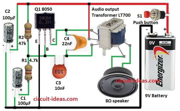
Main part is transistor 8050 Q1.
With capacitors C3 and C4 it makes sound frequency oscillator.
Capacitors C1 and C2 change sound slowly like real bird singing.
Signal goes to audio transformer and then to 8-ohm speaker for chirping sound.
Resistors R1 and R2 help transistor work good.
Circuit starts when button S1 is pressed and by letting current flow.
Formulas with Calculations:
Formulas and calculations for Simple Canary Bird Chirp Circuit:
1. Oscillation Frequency (f):
f = 1 / (2 * π * √(L * C))
where,
- L is the Inductance of transformer T1
- C is the Capacitance from C3 and C4
2. Time Constant for Chirp Modulation (τ):
τ = R * C
where,
- R is the effect of resistors R1 and R2
- C is the capacitance from C1 and C2
- τ controls how fast sound changes like bird chirp
3. Transistor Biasing:
Transistor must stay in active mode:
V_BE = 0.7V
R1 and R2 make voltage divider to give this voltage to transistor.
How to Build:
To build a Canary Bird Chirp Generator Circuit follow the below mentioned steps:
- Connect Q1 emitter to GND.
- Q1 base goes between R1 and R2.
- Q1 collector goes to one wire of transformer primary.
- Connect C3 between Q1 base and other wire of transformer primary.
- Connect R2, R1 and C1 in series from 9V to GND.
- C2 positive go to 9V and negative go to GND.
- Center wire of transformer primary go to 9V.
- Transformer secondary wires go to speaker.
- Switch S1 connects battery positive to circuit and negative to GND.
Conclusion:
This Canary Bird Chirp Generator Circuit show how oscillation and frequency changes the works.
It is good for beginners to learn transistor and sound making.
If required change capacitor values to make different bird sounds.
We can upgrade by adding amplifier or microcontroller for more chirps.
Leave a Reply