
To begin with, Power ON Delay Circuit using IC 555 give time gap between power ON and circuit starts.
When trigger comes, IC 555 work in monostable mode and give one output pulse for set time; furthermore, resistor R1 and capacitor C2 make timing part for delay.
When the circuit is OFF, the output stays low and after we apply power, capacitor C1 starts charging through R1.
Moreover, when voltage is ON capacitor reaches 2/3 of supply and 555 output goes high and circuit turns ON; after that capacitor discharge inside the timer and clears the circuit and delay next starts.
Circuit Working:
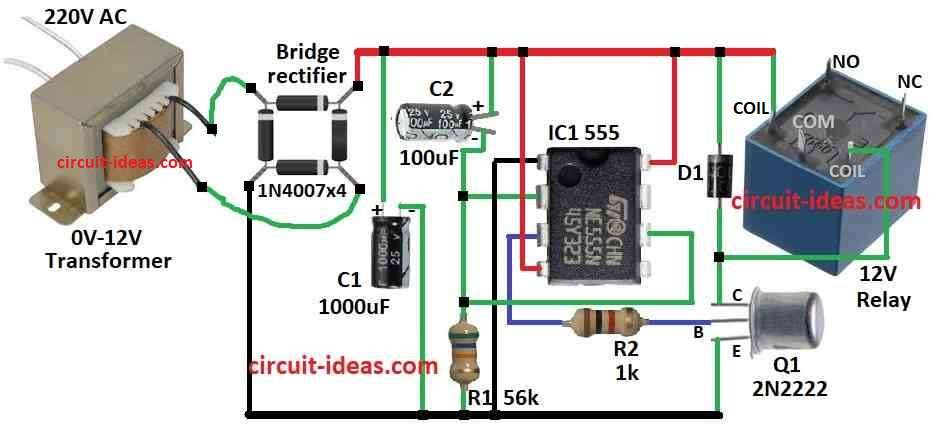
Parts List:
| Components | Values | Quantity |
|---|---|---|
| Resistors | 56k 1/4 watt | 1 |
| 1k 1/4 watt | 1 | |
| Capacitors | Electrolytic 1000μF 25V | 1 |
| Electrolytic 100μF 25V | 1 | |
| Semiconductors | IC 555 | 1 |
| Transistor 2N2222 | 1 | |
| 12V Relay | 1 | |
| Diode 1N4007 | 1 | |
| Bridge Rectifier 1N4007 | 4 | |
| 0V-12V Transformer | 1 |
Power On Delay Circuit with Relay Using 555 IC and Bridge Rectifier
Power Up and Rectification:
When plug in transformer give AC voltage, then bridge rectifier with 4 diodes 1N4007 change AC to DC and rest of circuit get power from this DC voltage.
Delay Timer with 555 IC:
555 IC work in monostable mode and power ON act like trigger and gives one high pulse for set time.
Timing and Delay:
Resistor R1 and capacitor C2 decide delay time and when power comes, C2 start charge through R1 and also during charging the output pin 3 stay low with relay OFF.
Triggering and Relay On:
When C2 voltage reach 2/3 of supply then pin 3 goes high and then this turn ON the relay; and then relay contact closes and device get power and turns ON.
Capacitor C1 Snubber:
C1 connect across relay coil and it absorb voltage spike when relay turns OFF and protects the circuit.
Reset and Next Cycle:
After delay C2 discharge through pin 7 which is inside 555 IC; output pin 3 goes low with relay OFF and device turns OFF.
After that, circuit waits for next power on to repeat.
Optional LED:
We can add LED with resistor to pin 3 and then LED stays OFF during delay and turns ON after delay finish.
Formula:
Delay Time Formula in Circuit:
Delay time T made by resistor R1 and capacitor C2 with 555 IC.
Formula is:
T = 1.1 × R1 × C2
where:
- T is the delay time in seconds
- R1 is the resistor value in ohms
- C2 is the capacitor value in farads
Use this formula to find delay time based on R1 and C2 and we can change delay by using different R1 or C2 values.
How to Build:
To build a Power ON Delay Circuit follow the below mentioned steps:
- First, pin 1 of IC 555 connects to ground
- Next, pin 2 and pin 6 of IC 555 connects together
- After that, C2 and R1 connects in series from pin 6 to ground
- Now pin 3 of IC 555 connects to base of transistor Q1 through R2, collector of Q1 connects to positive through diode D1 and then emitter of Q1 connects to ground.
- Then pin 4 and pin 8 of IC 555 connects to positive supply.
- Also, C1 connects from positive supply to ground.
- Relay coil connects one end to positive and other end between Q1 collector and D1
- Lastly, bridge rectifier connects as shown in circuit like AC in DC out
Conclusion:
Overall, this simple Power ON Delay Circuit is easy to build and when we connect our device the circuit gives small delay before turning ON.
Therefore, IC 555, R1 and C2 show the delay time and to adjust the delay, change the value of R1 or C2.