
This project show how to make very Simple Push Button Circuit with Arduino; as a push button act like an ON and OFF switch.
When we press button one time then LED changes its state, first press LED will turn ON and then second press LED will turn OFF; also it keeps doing the same.
Finally, all this happen with small Arduino code.
Arduino Code for 1 Push Button Switch:
int buttonPin = 2;
int ledPin = 13;
int buttonState;
int lastButtonState = 0;
int ledState = 0;

void setup() {
pinMode(buttonPin, INPUT);
pinMode(ledPin, OUTPUT);
}

void loop() {
buttonState = digitalRead(buttonPin);

if (buttonState == HIGH && lastButtonState == LOW) {
ledState = !ledState;
digitalWrite(ledPin, ledState);
delay(200);
}

lastButtonState = buttonState;
}
Arduino Code for 2 Push Button Switch:
int button1 = 2;
int button2 = 3;

int led1 = 13;
int led2 = 12;

int last1 = 0;
int last2 = 0;

int state1 = 0;
int state2 = 0;

void setup() {
pinMode(button1, INPUT);
pinMode(button2, INPUT);

pinMode(led1, OUTPUT);
pinMode(led2, OUTPUT);
}

void loop() {

int read1 = digitalRead(button1);
int read2 = digitalRead(button2);

if (read1 == HIGH && last1 == LOW) {
state1 = !state1;
digitalWrite(led1, state1);
delay(200);
}

if (read2 == HIGH && last2 == LOW) {
state2 = !state2;
digitalWrite(led2, state2);
delay(200);
}

last1 = read1;
last2 = read2;
}
Coding Explanation:
- button1 connect to pin 2.
- button2 connect to pin 3.
- led1 on pin 13.
- led2 on pin 12.
- read1 check button1.
- read2 check button2.
- If button1 go LOW to HIGH then Arduino toggle LED1.
- If LED1 is OFF then it turns ON.
- If LED1 is ON then it turns OFF.
- If button2 go LOW to HIGH then Arduino toggle LED2.
- If LED2 is OFF then it turns ON.
- If LED2 is ON then it turns OFF.
- last1 and last2 save old state to detect first press only.
- delay stop with double trigger.
Circuit Working:
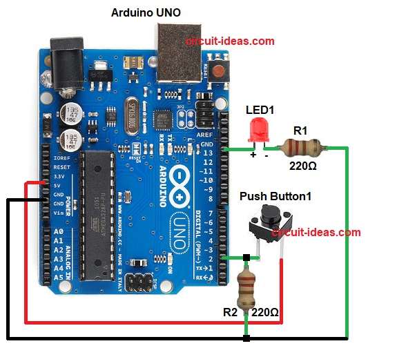
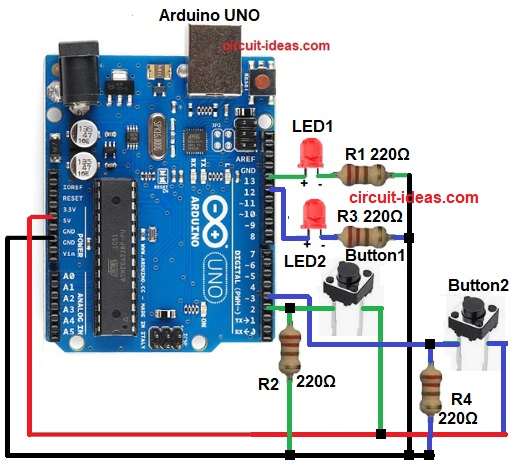
Parts List:
| Components | Quantity |
|---|---|
| Resistor 220Ω 1/4 watt | 4 |
| Arduino UNO | 1 |
| Push Buttons tactile switch | 2 |
| LED any 5mm | 2 |
| USB Cable | 1 |
| Breadboard | 1 |
When Arduino power start, LED is OFF and button 1 and button 2 both are in rest and both pins read LOW.
When we press button 1 then the pin 2 become HIGH and then Arduino sees change from LOW to HIGH on pin 2.
After that, Arduino flip LED state.
Moreover, if LED is OFF then it goes ON and if LED is ON then it goes OFF and when we release button 1 then pin 2 go LOW again and then Arduino wait for next press.
When we press button 2 then the pin 3 become HIGH and Arduino see change from LOW to HIGH on pin 3 and then Arduino again flip LED state.
If LED is ON then it goes OFF and if LED is OFF then it goes ON and button 1 and button 2 both do same toggle function.
Therefore, any button can change the LED state at any time, and the circuit repeats the same process every time the user presses a button.
Formula with Calculation:
LED resistor formula:
R = V / I
Arduino pin give around 5V and LED drop around 2V.
So resistor voltage = 5 – 2 = 3V.
If LED safe current = 20mA = 0.02A
Then:
R = 3 / 0.02
R = 150 ohm
Nearest safe value used is 220 ohm.
How to Build:
To build a Simple Push Button Circuit with Arduino with Arduino following are the steps for connections:
- First, gather all the parts as shown in circuit diagram.
- Next, push button1 connect one side to 5V and other side to Arduino pin 2.
- Also, same side connect R2 resistor to GND (pull-down).
- The push button2 connect one side to 5V and other side to Arduino pin 3.
- Also, same side connect R4 10k resistor to GND (pull-down).
- After that, LED1 positive connect pin 13 and LED1 negative to one end of 220 ohm resistor R1 and other of resistor go to GND.
- Now LED2 positive leg connect to Arduino pin 12 and LED2 negative leg connect to 220 ohm resistor R3 and also resistor other end to GND
- Lastly, Arduino 5V connect to breadboard + line and Arduino GND connect to breadboard – line.
Conclusion:
To conclude, this is an easy project for Simple Push Button Circuit with Arduino, as each button changes LED state every time we press it; also, the code is small and easy.
Furthermore, this circuit helps beginners understand digital input, output and toggle logic and we can also expand it for many automation projects.