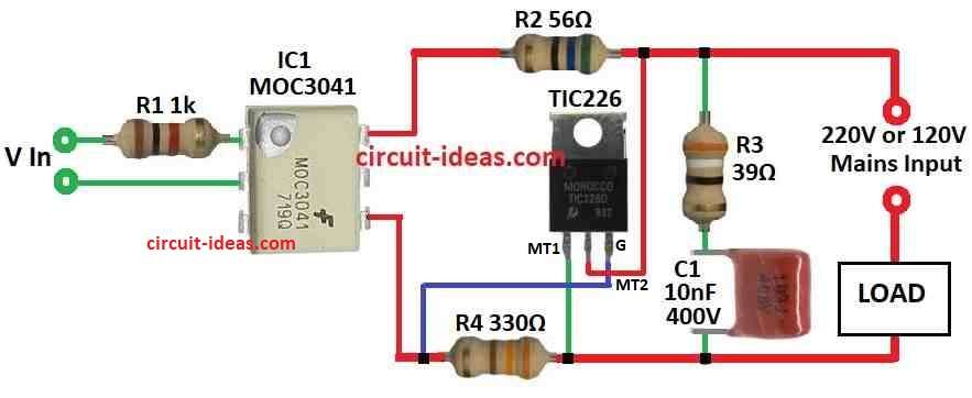
Simple Solid State Relay (SSR) circuit is like ON/OFF switch but with more better and modern.
Not like normal switch with moving parts but this one uses special electronics parts like transistor or triac for turning ON or OFF.
It works quietly with no noise and last a long time.
It is very good for many electronic projects.
Circuit Working:

Parts List:
| Category | Component | Quantity |
|---|---|---|
| Resistors (All resistors are 1/4 watt) | 1k | 1 |
| 56Ω | 1 | |
| 39Ω | 1 | |
| 330Ω | 1 | |
| Capacitors | PPC 10nF 400V | 1 |
| Semiconductors | Triac TIC226 | 1 |
| Opto-coupler IC MOC3041 | 1 |
IC like MOC3040 or MOC3041 works same like normal opto coupler but does not use phototransistor.
They use phototriac which can handle 100 mA 400V at 25°C.
One big good thing about this IC is it work with many SCR and triac.
Normal opto coupler with phototransistor is not always we can do this.
When making solid state relay (SSR) for 220V we need to pick right triac based on what load we are using.
For resistive load like bulb or heater TIC226D triac 400V is okay.
But for inductive load like motor or fan it is better to use TIC226M 630V triac.
Also capacitor C1 must have working voltage same or more than triac need.
For resistor R1 on input side we can find value using formula with input voltage Vin and LED current Ioc from MOC opto coupler.
Example:
If Vin is 12V and Ioc is 30mA standard for MOC3040 R1 = 356 ohm we can use 330 ohm which is close enough.
For MOC3041 with Ioc = 15mA R1 can be around 680 ohm.
This 220V SSR can handle up to 8 Amp.
If we need more power then we need to use stronger triac.
Formula:
Understanding R1 Formula in Simple SSR Circuit
Formula:
R1 = 1000 × Ioc × (Vin – 1.3)
where:
- R1 is the resistor value on input side which is in ohms Ω
- Ioc is the current going through LED in optocoupler which is in mA
- Vin is the input voltage in volts V
- 1.3 is the voltage drop across LED in volts
Explanation:
In simple SSR (solid state relay) circuit using optocoupler we can use this formula to find R1 resistor value.
This resistor stop too much current from going to LED.
How it work:
Ioc is current needed for LED inside optocoupler we can take this value from datasheet with this current be sure LED turn ON properly.
Vin – 1.3 is voltage across the resistor.
We minus 1.3V because LED already take that much voltage.
1000 is used because we change mA to A for correct calculation.
This way resistor R1 gives right current to LED which is not too high not too low.
Just correct for safe and proper circuit working.
How to Build:
To build a Simple Solid State Relay SSR Circuit we need to follow the below mentioned steps:
How to Make the Circuit:
- First collect all parts same like in circuit diagram.
- Connect one side of load to 220V power supply.
- Connect other side of load to MT1 pin of triac.
- MT2 pin of triac go to phase live wire of 220V AC.
- Take positive input voltage and connect it to anode of MOC3041 LED using resistor R1 in series.
- Connect negative input to cathode of MOC3041 LED.
Testing the Circuit:
- Give input voltage to MOC3041.
- Check if load resistive or inductive turn ON and OFF when input voltage change.
- It should work same like switch.
Safety Tips:
- Be sure all wires and parts are connected properly and with no loose wires
- Use safety items like gloves, goggles when working.
- Be careful this circuit uses high voltage of about 220V which can be dangerous.
Note:
- This is just a basic circuit and we can change or add more things if needed.
- Always check component datasheet and use good practice when making circuit.
Conclusion:
Simple Solid State Relay (SSR) circuit is electronic switch which uses solid state parts no moving or mechanical parts are used inside.
It gives many good things like strong working, long life and very fast switching.
Because of this it is good for many uses in industry machines and automation work.