This article is about Simple Time Delay LED Circuit using Transistor where the LED lit after a short wait; also the circuit needs transistor, capacitor and few resistors for delay.
In addition , the circuit is good for power light, warning light and timing project and it work with 10V DC and fits many electronics.
Circuit Working:
Parts List:
| Components | Values | Quantity |
|---|---|---|
| Resistors | 1k, 68k 1/4 watts | 1 each |
| Preset 100k | 1 | |
| Capacitor | Electrolytic 10µF 25V | 1 |
| Semiconductors | Transistor BC547 | 1 |
| LED 5mm 20mA | 1 |
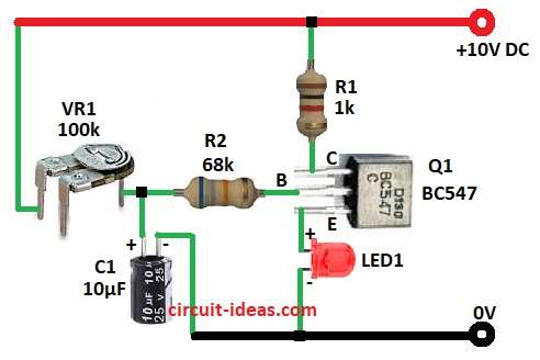
The circuit uses components such as transistor Q1, capacitor C1, resistors R1 and R2 and a VR1 preset.
First the capacitor charge through VR1 and when charge is high enough, then transistor Q1 is ON and LED1 lights.
Therefore, Delay time = VR1 resistance × C1 capacitance (RC constant).
Formulas with Calculations:
Below are the formulas with calculations for Simple Time Delay LED Circuit using Transistor:
Delay time T = 0.693 × VR1 × C1
Example: 0.693 × 100kΩ × 10µF = 0.693 sec (693ms).
Hence, for more delay, then use bigger preset VR1 or bigger C1 capacitor.
How to Build:
To build a Simple Time Delay LED Circuit using Transistor follow below steps for connection:
- First, take all parts from circuit diagram.
- Next, connect base of Q1 to one end of R2 and other end of R2 goes to one end of VR1 and other end of VR1 go to +10V.
- After that, connect collector of Q1 to one end of R1 and other end of R1 go to +10V.
- Now connect emitter of Q1 to anode of LED1 and cathode of LED1 go to GND.
- Finally, connect positive of C1 to point between R2 and VR1.
Conclusion:
To conclude, this is a Simple Time Delay LED Circuit using Transistor, it is a useful project and VR1 or C1 can adjust the delay.
Also, circuit is easy to build and need only few parts and is good for fun and learning.
Leave a Reply