This is one TV, Video Transmitter Circuit and it can send video from DVD, camera or other device to old TV in our house.
We do not need big parts or hard things, just small circuit and little care is all we need, so this type of circuit is good for fun and also for learning.
Circuit Working:
Parts List:
| Components | Values | Quantity |
|---|---|---|
| Resistors | All resistors are 1/4 watt unless specified | |
| 470Ω | 1 | |
| 100Ω | 1 | |
| 4.7k | 2 | |
| Preset 470Ω | 1 | |
| Capacitors | ||
| Ceramic 3.3pF | 1 | |
| Ceramic 2pF | 1 | |
| Ceramic 10pF | 1 | |
| Ceramic 100nF | 2 | |
| Electrolytic 100μF 16V | 2 | |
| Semiconductors | ||
| Transistor BFR91A | 1 | |
| Inductor Coil, air core, 2 turns, 3mm diameter using 0.5mm thick super enameled copper wire | 1 |
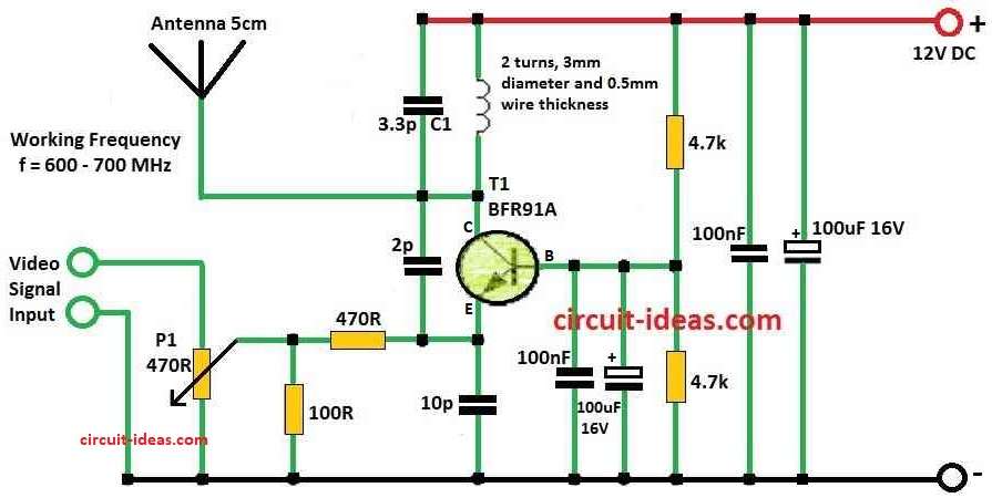
Firstly, the main part of TV transmitter is small oscillator with high-frequency NPN transistor like BFR90, BFR91A, BFR92 or BFR93.
The transistor is small TO50 type, which makes high-frequency waves and works as active part.
The LC circuit has one coil and capacitor C1 and these set frequency, so change coil and C1 to pick UHF frequency from 470 to 855 MHz.
Further, this circuit sends a signal on one TV channel, a simple 5 cm wire serves as the antenna, connecting directly to the oscillator to send the RF signal into the air.
Oscillator wave carrier change by video from camera or other source, then wave become strong or weak, so this is amplitude modulation.
Circuit uses 5 to 12V power and when power is ON, then oscillator sends RF signal.
Potentiometer P1 controls how much video changes wave like modulation depth, so we can adjust P1 to get better picture.
After power is ON, connect video source, then turn coil or parts by hand to tune.
Next, use old analog TV to find signal on UHF channel but usually, it is about 37 to 50, means 600 to 700 MHz, so this is tuning.
Formulas:
Here, are easy formulas for TV Video Transmitter Circuit and this circuit use LC formula to find frequency.
Resonant frequency (f) is:
f = 1 / 2π√LC
where:
- f is the working frequency of transmitter
- π is around 3.14159
- L is coil value is the inductance
- C is capacitor C1 value in capacitance
We can choose L and C value using circuit diagram to get right frequency.
Hence, this tell what channel our transmitter will work on.
This formulas help explain how frequency and modulation work in TV transmitter.
How to Build:
To build a TV/Video Transmitter Circuit, follow these steps for connections:
- For coil and capacitor C1 values look at the circuit diagram and these two parts decide what frequency transmitter will use.
- First, change coil and C1 to get frequency in UHF range from 470 to 855 MHz.
- Also, for antenna just connect a wire about 5 cm means 2 inch long straight to oscillator.
- Then give power to transmitter using 5 to 12V supply.
- Make live wires short, so it stop too much inductance and capacitance.
- Then to stop unwanted signals from parasitic effect put 100nF capacitor close to transistor.
- Also, use 100uF electrolytic capacitors in parallel to block noise from 50 Hz to hundreds of MHz.
Caution:
- Always know the legal rules before using UHF TV band for sending signal.
- Also, some countries do not allow this kind of broadcasting.
- If someone has legal trouble from using this it is not writers fault.
- Hence, do this project only under its countries laws and try it at ones own risk.
Conclusion:
To conclude, This TV Video Transmitter Circuit design can change based on what we need or want to do.
Also, we can buy ready-made transmitters that offer better sound, more channels, different frequencies, and stronger signals.
Therefore, before using always check the local rules about radio frequency broadcasting.