This project shows about Smooth Servo Rotation Circuit with Arduino and Potentiometer.
Turn the knob and see servo arm moves smooth from 0° to 180°.
Easy and fun to learn how Arduino reads analog signal and makes motion.
Its a good project for beginners in robotics, automation or motor control.
Arduino Coding:
#include <Servo.h>
Servo myservo;
int potPin = A0;
int val;

void setup() {
myservo.attach(9);
}

void loop() {
val = analogRead(potPin);
val = map(val, 0, 1023, 0, 180);
myservo.write(val);
delay(15);
}
Coding Explanation:
- Servo library is included to control servo motor easily.
- Servo is connected to pin 9 using attach function.
- Analog value from potentiometer is read using analogRead(A0).
- The map function changes range 0–1023 to 0–180.
- Servo moves to new angle using myservo.write(val).
- Delay gives smooth movement.
Circuit Working:
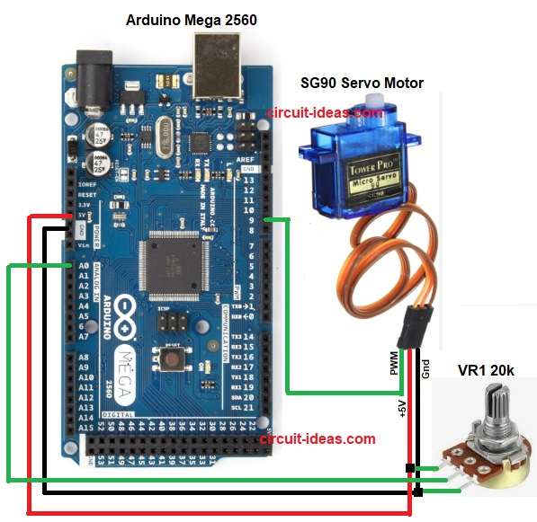
Parts List:
| Component Name | Quantity |
|---|---|
| SG90 Servo Motor | 1 |
| Arduino Mega 2560 | 1 |
| Potentiometer 20k | 1 |
Potentiometer gives analog voltage between 0V and 5V.
Arduino reads this voltage using analog pin A0.
Arduino converts it into a value between 0 and 1023.
This value is mapped to servo angle between 0 and 180 degrees.
When we rotate the potentiometer then the servo moves accordingly.
Formula with Calculation:
Below is the formula for Potentiometer output voltage = (Position / Full rotation) × 5V
Arduino analog value = (Voltage / 5V) × 1023
Example:
If potentiometer gives 2.5V then,
Analog value = (2.5 / 5) × 1023 = 511
Mapped servo angle = (511 / 1023) × 180 = 90 degrees
How to Build:
To build a Smooth Servo Rotation Circuit with Arduino and Potentiometer follow the below steps for connection:
- Assemble all the parts as shown in circuit diagram.
- Connect the servo motor red wire to Arduino 5V.
- Connect the servo black wire to GND.
- Connect the servo signal wire (usually yellow or orange) to Arduino pin 9.
- Connect the middle pin of potentiometer to Arduino analog pin A0.
- Connect one side of potentiometer to 5V.
- Connect the other side of potentiometer to GND.
Conclusion:
Smooth Servo Rotation Circuit with Arduino and Potentiometer is simple and easy to give it a try.
Potentiometer moves servo angle smoothly.
This project teaches analog input and PWM output.
Its useful in robotic arms, camera control, and small automation systems.
References:
Using the Arduino Uno to control multiple Servos via potentiometers
Leave a Reply