Want to roll a dice without touching it?
Build a digital dice using an Arduino Uno and an LCD screen; upload the code to Arduino Uno, test the button to ensure it generates random numbers (1–6).
This circuit works like real dice but uses electronics, as this is a simple and easy and a fun project for beginners.
Arduino Code:
#include <Wire.h>
#include <LiquidCrystal_I2C.h>

LiquidCrystal_I2C lcd(0x27, 16, 2);
int buttonPin = 2;
int buttonState = 0;

void setup() {
  lcd.init();
  lcd.backlight();
  pinMode(buttonPin, INPUT);
  lcd.setCursor(0,0);
  lcd.print("Electronic Dice");
  delay(2000);
  lcd.clear();
}

void loop() {
  buttonState = digitalRead(buttonPin);
  if (buttonState == HIGH) {
    int number = random(1,7);
    lcd.clear();
    lcd.setCursor(0,0);
    lcd.print("You Rolled:");
    lcd.setCursor(6,1);
    lcd.print(number);
    delay(1000);
  }
}
Circuit Working:
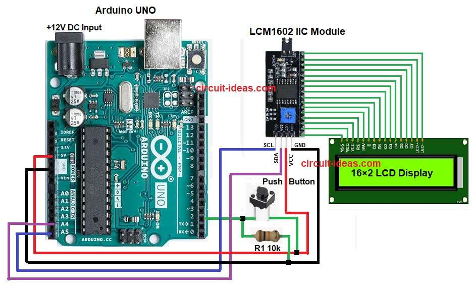
Parts List:
| Components | Quantity |
|---|---|
| Resistor 10k 1/4 watt | 1 |
| Arduino UNO | 1 |
| 16×2 LCD Display | 1 |
| LCM 1602 IIC Module | 1 |
| Push Button Switch (SPST) | 1 |
The 10k resistor keeps pin 2 LOW when we do not press the button.
The LCD shows nothing or the last number, but when we press the button, 5V goes to pin 2 and the Arduino reads a HIGH signal and generates a random number from 1 to 6.
Then the LCD displays that number as the dice result, and when the button releases, the system waits for the next press.
Formulas with Calculation:
Below is the basic formula for Digital Dice Circuit using Arduino Uno.
Pull-down resistor keeps pin low when button not pressed.
Formula is: R = (Vcc – Vinput) / I
here,
- Vcc is 5V
- Vinput is 0V
- I is 0.5mA (safe limit)
So R = (5 – 0) / 0.0005 = 10k (approx).
Hence, this value matches the 10k resistor used in circuit.
How to Build:
To build a Digital Dice Circuit using Arduino Uno follow the below steps for connection:
- First, gather all the parts as shown in circuit diagram.
- Next, button one side connect to 5V and button other side connect to pin 2
- After that, 10k resistor connect between pin 2 and GND.
- Now LCD I2C Module VCC pin connect to 5V
- Then LCD I2C Module GND pin connect to GND
- Further, LCD I2C Module SDA pin connect to A4
- Finally, LCD I2C Module SCL pin connect to A5
Conclusion:
To conclude, this Digital Dice Circuit using Arduino Uno is easy to make, as it works like electronic dice.
We can also learn how button works and we can see how LCD shows number; here Arduino makes random number, furthermore, its good for beginners which helps to practice coding and circuit.

Leave a Reply