Want to build a smart obstacle detector without using Arduino? then this simple project uses a 555 timer and an ultrasonic sensor to sense distance and control a DC motor automatically.
Also, it is easy to make with low-cost and perfect for beginners in electronics; therefore, this Obstacle Detection Circuit with 555 Timer and Ultrasonic Sensor is a cool DIY project, one should definitely give a try for.
Circuit Working:
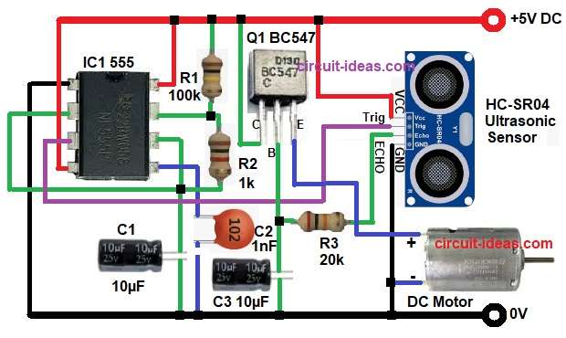
Parts List:
| Components | Values | Quantity |
|---|---|---|
| Resistors (All resistors are 1/4 watt unless specified) | 1k | 1 |
| 100k | 1 | |
| 20k | 1 | |
| Capacitors | Electrolytic 10µF | 2 |
| Ceramic 1nF | 1 | |
| Semiconductors | IC 555 Timer | 1 |
| Transistor BC547 | 1 | |
| DC Motor | 1 | |
| HC-SR04 Ultrasonic Sensor | 1 |
The above circuit is in astable mode (continuous pulse generator) and the ultrasonic sensor HC-SR04 sends and receives ultrasonic waves; also it works as an oscillator.
The pulse frequency depends on resistors R1, R2 and capacitor C1 and these pulses keep triggering the ultrasonic sensor again and again.
Then sensor keeps sending and receiving ultrasonic waves continuously.
When object comes near, echo signal activates transistor and motor turns ON and when object goes away then there is no echo and motor stops.
Formula with Calculation:
555 timer gives pulse time by formula:
T = 1.1 × R1 × C1
Take the values:
R1 = 100kΩ = 100000Ω
C1 = 10µF = 0.00001F
T = 1.1 × 100000 × 0.00001
T = 1.1 sec
So output stays HIGH for about 1.1 seconds and then in this time, transistor is ON and motor runs for short time.
How to Build:
To build a Obstacle Detection Circuit with 555 Timer and Ultrasonic Sensor follow the below steps:
- First, take all parts same as circuit diagram.
- Next, connect HC-SR04 sensor VCC to +5V and GND pin to ground.
- Then trig pin connect to pin 3 OUT of 555 timer and echo pin goes through resistor R3 to transistor base.
- After that connect 555 timer IC1 pins like this: pin 1 GND to ground and pin 2 TRIG connect to pin 6 THR.
- Now pin 3 OUT connect to sensor Trig pin and pin 4 RESET to +5V.
- Further, pin 5 CV connect to ground through capacitor C3 and then pin 6 THR connect to pin 2 TRIG.
- Also, pin 7 DIS go between resistors R1 and R2 and pin 8 VCC go to +5V.
- Next, connect transistor Q1, base connect with resistor R3 and capacitor C2, collector connect to +5V and emitter connect to positive of DC motor.
- Finally, motor negative goes to ground.
Conclusion:
To conclude, this Obstacle Detection Circuit with a 555 Timer and Ultrasonic Sensor works simply and easily because it does not require an Arduino.
Also, ultrasonic sensor finds object and 555 timer gives short pulse and then transistor turns motor ON and when object goes away then motor stops.
Additionally, it is good for small automation and learning projects.

Leave a Reply