Stereo preamp is important part of audio system.
It makes weak sound signals from mic or other devices and is stronger for better use.
LA3161 is 2-channel preamp chip made for car stereo.
It has low noise, works well and needs few extra parts.
It has built-in voltage control to cut noise and make sound better.
This Stereo Preamplifier Circuit using IC LA3161 explains how LA3161 preamp circuit works, how to build it, with formulas and ends with a conclusion.
Circuit Working:
Parts List:
| Component | Specification | Quantity |
|---|---|---|
| Resistors (All resistors are 1/4 watt unless specified) | 100k | 2 |
| 7.5k | 2 | |
| 100Ω R5 and R6 | 2 | |
| 150Ω | 1 | |
| Capacitors | Ceramic 1000pF | 2 |
| Ceramic 0.01µF 2 | 2 | |
| Electrolytic 47µF 25V | 3 | |
| Electrolytic 10µF 25V | 4 | |
| Semiconductors | IC LA3161 | 1 |
This circuit runs on 12V power.
LA3161 IC can take up to 18V and 200mW power.
Audio left and right go in through C8 pin 1 and C9 pin 8 to block DC.
C10 and C11 remove high-frequency noise.
IC boosts weak audio signals.
R1, R4, C1 and C2 control gain and frequency.
C4 and C5 let only AC audio go to output.
Outputs left and right can go to next amplifier or be used directly.
C6 and C7 keep power stable and reduce noise.
Formulas with Calculations:
Here are simple formulas for LA3161 stereo preamp circuit:
Voltage Gain (AV):
AV = R4 / R3
= 100k / 7.5k = 13.33
Signal gets about 13 times louder.
Cutoff Frequency (fC):
fC = 1 / (2πRC)
= 1 / (2π × 100k × 10nF) = 159.15 Hz
This sets the low-frequency limit of the sound.
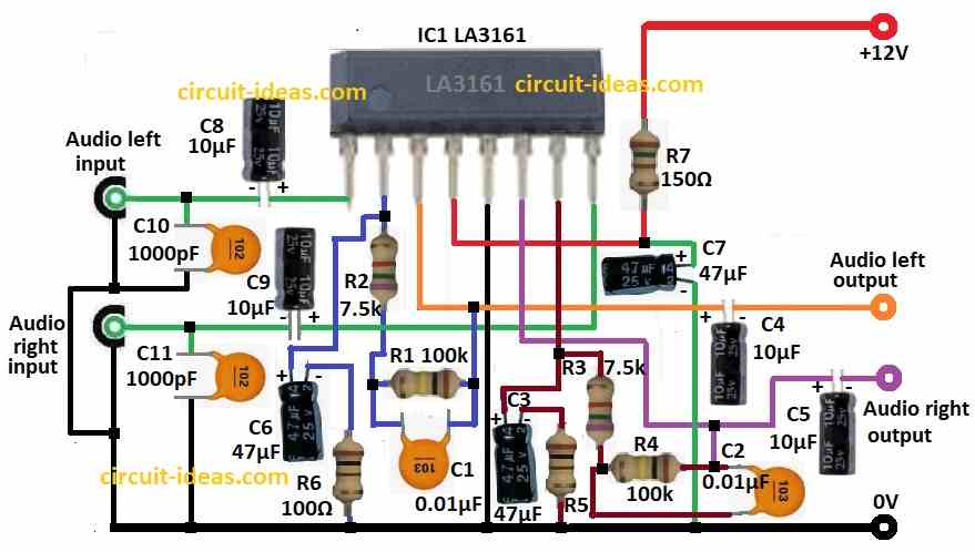
How to Build:
To build a Stereo Preamplifier Circuit using IC LA3161 following are the steps we need to follow the assembling:
- Collect all parts shown in the circuit diagram.
- Connect pin 1 of LA3161 to audio left input using capacitor C8.
- Add capacitor C10 between C8 and ground (GND) to filter noise.
- From pin 2 connect R2, R1 and C1 in series.
- Also connect capacitor C6 and resistor R6 from pin 2 to GND.
- Connect pin 3 to audio left output through capacitor C4.
- Connect pin 4 to +12V supply through resistor R7.
- Also place capacitor C7 between +12V and GND for power filtering.
- Connect pin 5 directly to GND.
- Connect pin 6 to audio right output through capacitor C5.
- From pin 7 connect R3, R4 and C2 in series.
- Also connect capacitor C3 and resistor R5 from pin 7 to GND.
- Connect pin 8 to audio right input using capacitor C9.
- Add capacitor C11 between C9 and ground to reduce noise.
Conclusion:
Stereo Preamplifier Circuit using IC LA3161 is easy to make and works well.
It uses few parts and boosts sound nicely.
We can change part values to control sound gain and frequency.
It is good for people who love electronics and audio projects.