
Today, many small devices need low voltage for example 1.5V or 3V.
A USB port provides a 5V output, so this circuit uses a buck converter to reduce the voltage to 1.5 V or 3 V.
The MC34063 IC controls the conversion, making the circuit low cost, easy to build, reliable, and efficient; the IC is also widely available and popular among electronics hobbyists and professionals.
Moreover, this circuit is efficient as it wastes less power, so battery life improves.
Circuit Working:
Parts List:
| Components | Values | Quantity | Remarks |
|---|---|---|---|
| Resistors | 0.47Ω 1/2 watt | 2 | |
| 220Ω / 1.5k | 1 | R1 (Voltage set for 1.5V or 3V) | |
| 1k | 1 | R2 (Voltage set for 1.5V or 3V) | |
| Capacitors | Ceramic 680pF | 1 | |
| Electrolytic 220uF 25V, 470uF 25V | 1 each | ||
| Semiconductors | IC MC34063 | 1 | |
| Inductor Coil 100uH | 1 | ||
| Schottky Diode 1N5819 | 1 | ||
| USB Type-A / Micro USB for 5V input supply | 1 |
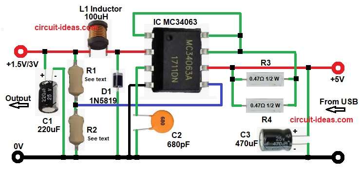
To begin with, this circuit works as a step-down converter, also known as a buck converter, as it accepts a 5V input and provides a regulated output of either 1.5V or 3V.
First, 5V comes from USB and then capacitor C3 removes noise, then MC34063 is main IC and it is heart of circuit which starts oscillating and it controls switching.
Pin 2 drives the internal switch, allowing current to flow through inductor L1, then the inductor stores energy while the switch remains ON.
When the switch turns OFF, the inductor releases the stored energy through diode D1, which charges output capacitor C1.
At same time feedback resistors check output and voltage goes to pin 5 and IC compares voltage inside, if voltage is high the switching becomes less and if voltage is low the switching becomes more.
So, output voltage stays constant.
Formula with Calculation:
The MC34063 feedback reference is 1.25V
Formula:
Vout = 1.25 × (1 + R1 / R2)
For 1.5V output:
We have taken R2 = 1k
Now lets calculate R1:
1.5 = 1.25 × (1 + R1 / 1000)
1.5 / 1.25 = 1 + R1 / 1000
1.2 = 1 + R1 / 1000
R1 / 1000 = 0.2
R1 = 200Ω
Final values for 1.5V is:
R1 = 220Ω (standard value)
R2 = 1kΩ
This gives around 1.52V which is perfect for 1.5V devices.
For 3V output:
We have kept R2 = 1k
Now calculate R1:
3 = 1.25 × (1 + R1 / 1000)
3 / 1.25 = 1 + R1 / 1000
2.4 = 1 + R1 / 1000
R1 / 1000 = 1.4
R1 = 1.4kΩ
Final values for 3V is :
R1 = 1.5kΩ (standard value)
R2 = 1kΩ
Hence, this gives around 3.1V which is safe and acceptable.
Summary for 1.5V / 3V:
| Output Voltage | R1 Value | R2 Value |
|---|---|---|
| 1.5V | 220Ω | 1k |
| 3V | 1.5k | 1k |
How to Build:
To build a 5V USB to 1.5V or 3V DC Converter Circuit follow the below steps for connection:
- First, collect all components as per circuit.
- Then connect IC pin 1 and joins with IC pin 7 and pin 8.
- Next, connect IC pin 2 and this pin goes to output side through diode D1 cathode.
- Then connect inductor L1 and after that connect resistor R1.
- Also, connect capacitor C2 positive.
- After this connect IC pin 3 to capacitor C1 from pin 3 to GND.
- Then connect IC pin 4 and this pin goes directly to GND.
- Next, connect IC pin 5 which connect it between resistor R1 and R2.
- Afterwards, connect IC pin 6 which connects it to +5V supply.
- Then connect IC pin 7 which connect one end of resistor R3 to pin 7, also other end of R3 goes to pin 6.
- Now connect IC pin 8 which join with pin 7.
- After this, connect input capacitor C3 whose positive goes to +5V input and negative goes to GND.
- Lastly, connect output capacitor C2 whose positive goes to 1.5V or 3V output and negative goes to GND and finally, check all connections and then power ON the circuit.
Conclusion:
To conclude, this 5V USB to 1.5V or 3V DC Converter Circuit is very useful, as it converts USB 5V to low voltage, therefore beginners can build it easily.
The MC34063 IC simplifies the design because it requires only a few external components, it also provides reliable and efficient operation, making the circuit suitable for professional use.
At last, this buck converter circuit is a good choice one should give it a try for.