Photography flash units need correct timing.
However, many old flash units do not have trigger input, so a Solar Cell Based Camera Flash Trigger Circuit is useful.
This circuit is very simple as it uses very few components and also it does not need any battery.
The circuit works using light only and when a main camera flash fires then this circuit detects light.
Then it instantly triggers another flash, because of this it is called a slave flash trigger.
It is useful in studio photography and it is also good for learning electronics basics.
Circuit Working:
Parts List:
| Components | Value | Quantity |
|---|---|---|
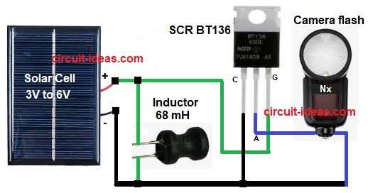
| Thyristor SCR | BT136 | 1 |
| Inductor / Coil | 68 mH 500 mA | 1 |
| Solar Cell | 3V to 6V small panel | 1 |
| Flash Unit | Camera flash | 1 |
This circuit uses only four main parts: solar cell, inductor coil, SCR BT136, camera flash unit.
First, solar cell is placed facing light and it must see the camera flash.
When main camera flash fires the strong light falls on solar cell and because of this the solar cell makes a small voltage pulse.
This voltage pulse goes to SCR gate pin and then the SCR turns ON very fast.
At same time the inductor gives its stored energy, so current starts flowing through the SCR.
Because of this the flash unit gets trigger signal and flash fires at same time.
After flash fires the current stops and then SCR turns OFF by itself.
So the slave flash works instantly with no delay in flashing.
How to Build:
To build a Solar Cell Based Camera Flash Trigger Circuit follow the below connection steps:
- Start, the circuit by gathering all the circuit parts:
- Then connect solar cell positive to one end of inductor.
- Connect other end of inductor to SCR gate pin.
- Connect SCR anode to flash trigger terminal.
- Connect SCR cathode to common ground.
- Connect solar cell negative to ground.
- Connect flash negative terminal to ground.
- Make sure polarity is correct and use a proper insulated wires.
- Do not touch flash terminals directly high voltage may be present.
Conclusion:
This simplest Solar Cell Based Camera Flash Trigger Circuit is a very low cost project.
It is easy to understand and build, because it uses solar cell and no power supply is needed.
Also SCR gives fast and accurate triggering.
So this circuit is perfect for beginners as it is also helpful for photographers using old flashes.
Finally, this circuit proves that simple designs still work best.
Leave a Reply