This post teaches how to make Simple 220V AC Light Dimmer Circuit for home lights; also with this dimmer we can make light more or less bright by turning OFF current slowly.
Note: Working with high voltage is not safe; good electrician should fix this in house and only do if big person is watching.
Also, new electronic beginners should not try this.
What is AC Light Dimmer Circuit:
An AC light dimmer is an electrical device that changes the brightness of a light, mostly for incandescent bulbs.
Also, the main reason to use dimmer is to change power going to light so user can choose how much bright they want.
To do this, the circuit controls the voltage or current that goes to the bulb so the light becomes brighter or dimmer.
Understanding Triac Dimmers:
Triacs used a lot in circuits to turn AC things ON or OFF, as they work when to get DC trigger from outside.
However, people mostly use them for full ON or OFF switching, but they also control AC power in many applications.
Also, like in dimmer switch triac only work in some parts of AC wave and this makes output AC smaller than input AC.
Moreover, dimmer switch for normal light bulb is good example as it changes power to light so light become more or less bright.
Circuit Working:
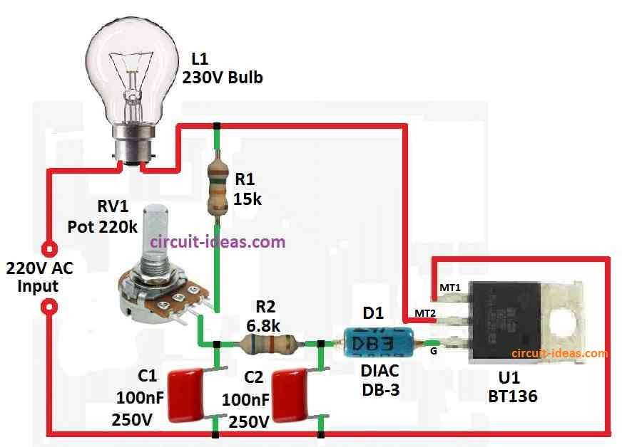
Parts List:
| Components | Values | Quantity |
|---|---|---|
| Resistors | 15k CFR, 6.8k CFR 1/4 watts | 1 each |
| Potentiometer 220k | 1 | |
| Capacitors | PPC 100nF 250V | 2 |
| Semiconductors | Transistor BT136 | 1 |
| DIAC DB-3 | 1 | |
| Incandescent Bulb 230V | 1 |
When AC power goes in circuit after some time C2 get full charge and then diac gets enough voltage to start working; but when diac work then triac also start to conduct.
But when this happen C2 loses charge and goes down below diac working level and because of this diac and triac stop again and this happen many times in each AC wave.
Also, this make the light less bright because voltage goes down in a controlled way.
Here, C1 is not necessary for normal bulbs, but it becomes very important when we use inductive loads such as motors or fans.
Inductive loads can send power back into the circuit, which can disturb the charging of C2.
Furthermore, C1 help fix this problem which gives small power bursts to keep triac working even when C2 is empty;
Also while working these dimmers make lot of radio noise like RF noise.
So we need to add RC network to dimmer to reduce this noise and keep it clean.
Formulas:
Basic 220V AC Light Dimmer Circuit:
To make basic light dimmer for 220V AC we have used TRIAC, DIAC and some other parts and these kind of circuit changes phase angle of AC voltage to control how much power goes to light bulb.
Time Calculation:
The resistor and capacitor in the RC network show how long the delay lasts in the phase control circuit.
Time constant (𝜏 tau) tell us how much delay before TRIAC turn ON; also we use below formula to find delay angle (α):
α = 1 / 2πfRC
where:
- f is AC frequency in most places around 50 Hz.
- R resistance with potentiometer + fixed resistor.
- C is total capacitor value for C1 and C2 in farads.
Each time AC cycle happens TRIAC turn ON at a certain angle;
So we can turn the potentiometer to change this angle and this changes how bright the bulb becomes.
Hence, by changing phase angle we make the bulb go dim or bright and this is how basic dimming works.
How to Build:
To build a Simple 220V AC Light Dimmer Circuit follow the below mentioned steps:
Triac Connection:
- First, connect MT1 pin of triac to a live wire from AC mains.
- Then connect a bulb as load to MT2 pin.
- After that, gate of triac connects through diac and connect where R1 and C2 meet or just connect like show in diagram.
Set Up Potentiometer:
- Also, one side of potentiometer connect to point where R1 and C2 join and other side connect to common point of load.
- Then the middle pin the wiper of potentiometer goes to AC neutral.
C1 Connection:
- Now if using inductive load then connect one side of C1 to point of R1 and C2 and other side of C1 goes in parallel with load.
Power Source:
- Also, AC phase wire connect to triac MT1.
Ground Optional:
- For safety connect ground to circuit.
Testing and Changing:
- Then turn ON power and check if bulb lights up and turn potentiometer knob to make light more or less bright.
- Also, check whether the RC network reduces RF noise.
Safety Tips:
- Remember that all circuits here connect directly to AC mains, so take great care while touching or testing them, especially when the power is ON.
Conclusion:
Overall, if we follow steps properly and stay safe we can build a Simple 220V AC Light Dimmer Circuit by using a Triac; also we can change how bright the light bulb glows.
Leave a Reply