This one is a special and Simple Skin Biofeedback Circuit which help people learn about skin, it uses sticky pads put on skin to catch small electric signal.
Also, signal change when person feel more calm or is not calm; hence, the circuit show this change maybe with light or sound so person can learn to relax better.
Circuit Working:
Parts List:
| Components | Values | Quantity |
|---|---|---|
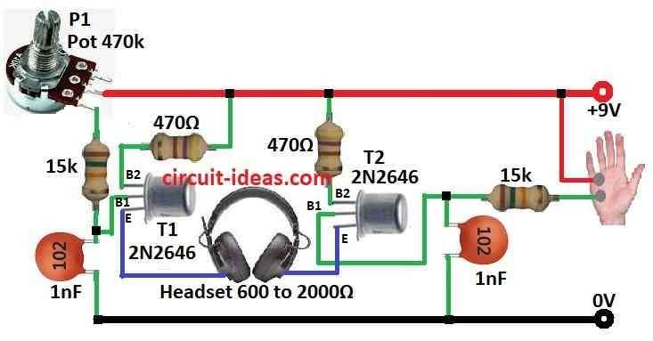
| Resistors | 15k 1/4 watt | 2 |
| 470Ω 1/4 watt | 2 | |
| Potentiometer 470k | 1 | |
| Capacitors | Ceramic 1nF | 2 |
| Semiconductors | UJT 2N2646 | 2 |
| Headset 600 to 2000Ω | 1 |
This simple circuit gives special kind of biofeedback, as it works because when person relax mores skin resistance go up.
Also, this change in resistance make oscillator in circuit using transistor T2 changes the sound.
Here, two ring type electrodes go on two fingers of one hand, speaker make sound and sound pitch show how relaxed person is; more relaxed mean sound get lower.
Furthermore, transistor T1 forms another oscillator that produces a sound and we can adjust its sound with knob P1 to match the first sound when the person is most relaxed.
Therefore, when both sounds match in the stereo headphones, both sides of the brain work in sync and the person feels very relaxed.
Formulas:
In this circuit diagram signal from skin electrodes connects to two transistors T1 and T2 to make it stronger means to amplify.
P1 is small knob potentiometer which changes how sensitive the circuit is.
Two 15k resistors, R1 and R2 supply power to the transistors.
C1 and C2 are two 1nF capacitors which help to remove high frequency noise which are the the unwanted tiny signals.
Here is simple formula for how much circuit makes signal stronger with gain:
Gain = (R2 / R1) * (1 + (R3 / R4))
where:
- Gain mean how much circuit boost the small signal from skin.
- R1, R2, R3, R4 are values of resistors and other parts like potentiometer and electrodes.
So this formula just show how strong circuit make small signal and bigger gain mean better signal for see skin resistance change.
How to Build:
To build a Simple Skin Biofeedback Circuit follow the below mentioned connection steps:
- First, take one electrode and connect it to the middle pin of T2 and other electrode connects to positive power.
- Now make first oscillator using T2 and this one changes sound based on skin resistance between electrodes.
- Then make second oscillator using T1.
- After that, connect both oscillator outputs like T1 and T2 to stereo headset and then use knob P1 to change second oscillator sound.
- Wear headset and listen to both sounds from the two oscillators.
Note:
- Turn knob P1 until second sound matches first one when we feel very calm and relaxed and when both sounds are same it means we have reached the deep relaxation where brain is in sync.
Conclusion:
To conclude, Simple Skin Biofeedback Circuit is useful tool to check and control stress, it look at how skin resistance change and give live feedback.
Also, this help people learn how to relax better and lower its stress.
Leave a Reply