In this post we will show how to make Simple Heartbeat Monitor Circuit using Arduino.
First, when we put finger on sensor it count heartbeats per minute and this is important because heartbeat tells doctor about our health.
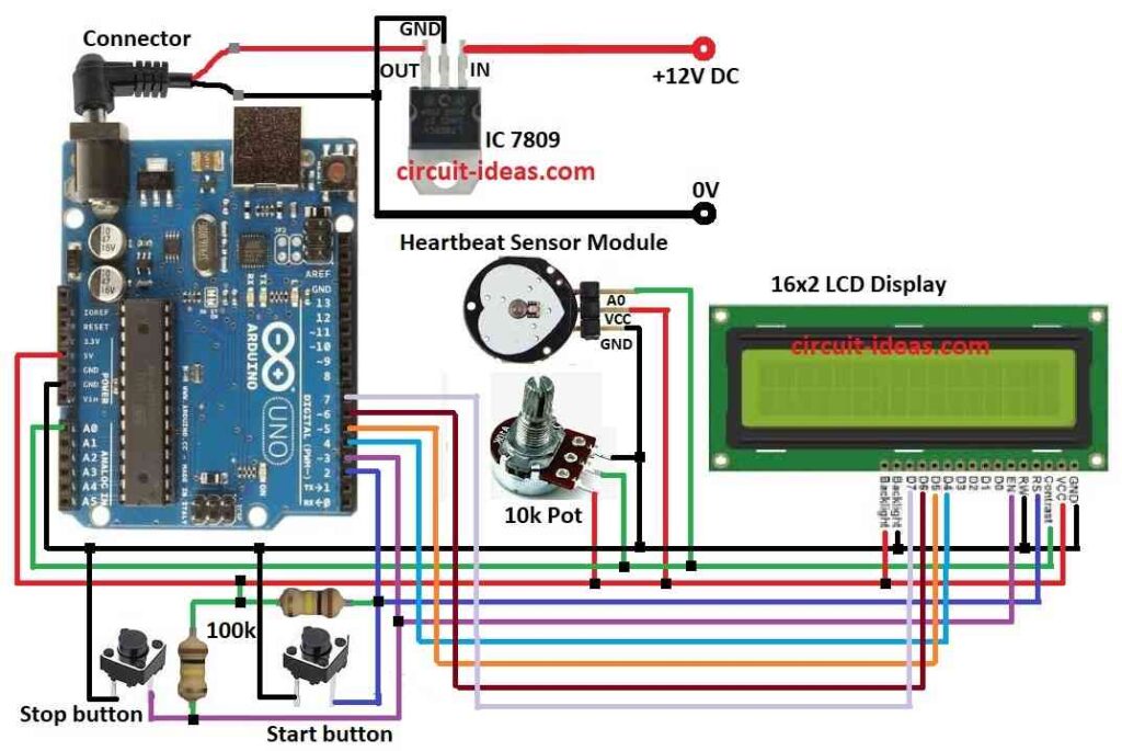
Here, we use Arduino UNO, LCD screen, two buttons, one resistor and heartbeat sensor to build it; furthermore, sensor catches heartbeat signal and Arduino read it and show heartbeat on screen.
Finally, two buttons control screen and heartbeat check.
Arduino Code:
#include <LiquidCrystal.h>

// Define pins for components
const int heartRatePin = A0;
const int startButtonPin = 2;
const int stopButtonPin = 3;
const int lcdContrastPin = 4;

// Create LCD object
LiquidCrystal lcd(12, 11, 5, 4, 3, 2);

void setup() {
  // Set pins as input or output
  pinMode(heartRatePin, INPUT);
  pinMode(startButtonPin, INPUT_PULLUP);
  pinMode(stopButtonPin, INPUT_PULLUP);
  pinMode(lcdContrastPin, OUTPUT);

  // Initialize LCD display
  lcd.begin(16, 2);
  lcd.setCursor(0, 0);
  lcd.print("Heartbeat Monitor");
}

void loop() {
  // Read heart rate sensor value
  int sensorValue = analogRead(heartRatePin);

  // Calculate heart rate (adjust factors as needed)
  int heartRate = (sensorValue * 60) / 1023;

  // Display heart rate on LCD
  lcd.setCursor(0, 1);
  lcd.print("HR: ");
  lcd.print(heartRate);
  lcd.print(" BPM");

  // Check for button presses
  if (digitalRead(startButtonPin) == LOW) {
    // Start heart rate measurement
    // ... (your code here)
  }

  if (digitalRead(stopButtonPin) == LOW) {
    // Stop heart rate measurement
    // ... (your code here)
  }
}
Code Explanation:
- Arduino read heart rate sensor value from A0 pin (analog read).
- Heart give tiny electric signals and this make value go up and down.
- To make reading better, code uses filter or average to remove noise.
- The Arduino converts analog values from 0 to 1023 into BPM (beats per minute)
- Sensor setting and how sensitive it is decide how value change to BPM.
- LCD show “HR:” and number with “BPM” after it.
- Start and stop buttons use pull-up resistor.
- Button normally high (1) go low (0) when pressed.
- Code checks the button press and start button begin heartbeat check and this stops the button and pauses it.
Circuit Working:
Parts List:
| Components | Quantity |
|---|---|
| Resistors | |
| 100k 1/4 watt | 2 |
| Potentiometer 10k | 1 |
| Semiconductors | |
| Arduino UNO | 1 |
| Heart Beat sensor module | 1 |
| 16×2 LCD | 1 |
| Push button tactile switches | 2 |
| IC 7809 | 1 |
Arduino UNO get steady 9V power using 7809 voltage regulator and this is good because Arduino need 5V to work.
The heartbeat sensor module detects the heartbeat by using infrared light to monitor changes in blood flow when the heart pumps, then the sensor converts these changes into small electrical signals (pulses).
Then sensor send analog signal to Arduino UNO and Arduino read this signal, calculate heart rate and show it on LCD.
After that, press start button pin 2 to begin and it will turn on sensor, clear old data and set LCD for display; then press stop button to pause or stop which then turns OFF sensor, save data and show stop message on screen.
Also, the potentiometer changes the LCD contrast.
How to Build:
To build a Simple Heartbeat Monitor Circuit using Arduino following are the steps to follow:
- First, collect all parts same like in circuit diagram.
- Next, connect 7809 IC to give steady 9V DC to Arduino.
- Then connect 10k pot 1st pin to LCD VCC, 2nd pin of 10k pot goes to LCD contrast pin and then 3rd pin of 10k pot goes to LCD GND.
- Also, one leg of start button goes to Arduino pin 2, other leg of start button goes to GND.
- After that, one leg of stop button goes to Arduino pin 3 and then other leg of stop button goes to GND.
- Now put 100k resistor between pin 2 and 5V on Arduino and then put other 100k resistor between pin 3 and 5V on Arduino.
- Then 1st pin of heartbeat sensor goes to 5V on Arduino, 2nd pin of heartbeat sensor goes to GND and then 3rd pin of heartbeat sensor goes to A0 on Arduino.
- Finally, connect LCD R/W pin to GND on Arduino, connect LCD backlight cathode to GND and then connect LCD backlight anode to 5V on Arduino.
Below table shows connections of an LCD Display to Arduino board:
| Arduino Pin | LCD Pin | Description |
|---|---|---|
| 5V | VCC | Power supply |
| GND | GND | Ground |
| D2 | RS | Register select |
| D3 | E | Enable |
| D4, D5, D6, D7 | D4, D5, D6, D7 | Data pins |
Conclusion:
Overall, this project for Simple Heartbeat Monitor Circuit using Arduino show simple heartbeat monitor; also code give basic way to find and show heart rate.
Moreover, it also tell how to connect parts and make circuit and we can also make it better by adding features like to save heart rate data, show average heart rate and give light or screen alerts.
Leave a Reply