Today solar power is very important because world need clean and green energy.
Solar tracking help make solar panels work better.
It move solar panel with sun all day so panel get more sunlight and gives more power.
Solar Tracking Circuit using Arduino is smart, DIY and fun project.
Arduino is open-source board which is easy to use for making tracking system.
With this project students or hobby people can build solar tracker that follow sun and make more energy.
This article show how Arduino solar tracker makes panels more efficient.
It uses Arduino board, IC 7809, servo motor, solar panel, LDRs and resistors.
Project uses simple sensors and motors to teach electronics and coding in easy way.
It is good for learning and good for environment too!
Coding:
#include <Servo.h>

Servo myservo;  // create a servo object to control the servo

const int LDR1 = A0;  // analog pin for LDR 1
const int LDR2 = A1;  // analog pin for LDR 2

int LDR1Value = 0;
int LDR2Value = 0;

void setup() {
  myservo.attach(9);  // attach the servo to pin 9
  Serial.begin(9600);  // initialize serial communication
}

void loop() {
  LDR1Value = analogRead(LDR1);
  LDR2Value = analogRead(LDR2);

  // calculate the difference in light levels
  int difference = LDR1Value - LDR2Value;

  // adjust the servo position based on the difference
  if (difference > 100) {
    myservo.write(90);  // turn right
  } else if (difference < -100) {
    myservo.write(0);  // turn left
  } else {
    myservo.write(45);  // maintain current position
  }

  Serial.println(difference);  // print the difference for debugging
  delay(1000);  // delay for 1 second
}
Code Explanation:
- #include add servo library which give tools to control servo motor.
- const int LDR1 = A0; sets LDR1 to pin A0 and this pin read light from first LDR.
- const int LDR2 = A1; set LDR2 to pin A1 and this is for second LDR.
- analogRead() read voltage from analog pin.
- attach() and write() from servo library which is used to connect and move servo motor.
- if-else then use difference value to decide what to do.
- Serial library helps to send and get data with computer using USB.
- delay(1000); wait 1 second before repeat loop.
- void loop() { … } this function run again and again.
- Serial.println(difference); show value of “difference” in serial monitor for checking.
- myservo.attach(9); connect servo motor to pin 9.
- Serial.begin(9600); starts serial communication at 9600 speed and help check program output.
Circuit Working:

Parts List:
| Component | Quantity |
|---|---|
| Resistors | |
| 10k 1/4 watt | 2 |
| LDR (Light Dependent Resistor) | 2 |
| Semiconductors | |
| Arduino Uno Board | 1 |
| IC 7809 | 1 |
| Servo Motor 5V | 1 |
| Solar Panel 12V 1 Amp | 1 |
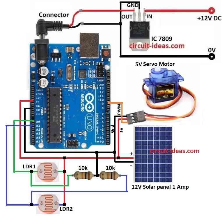
This Solar Tracking using Arduino is an easy project.
Wiring connection are shown in circuit diagram.
Two LDRs placed on both sides of solar panel.
LDRs changes resistance when sunlight changes during day.
10k resistors and LDRs make voltage divider circuit.
This circuit gives two voltage signals based on light each LDR gets.
These voltages goes to Arduinos analog input pins.
Arduino reads values to compare light on both the sides.
A servo motor is used to move the solar panel.
Servo motor is good because it moves panel in small steps and follows sun all day.
Servo is used here runs on 5V.
Arduino sends control signal to servo after checking light difference.
Servo turns panel to face sun better.
To power Arduino and servo safely and IC 7809 is used to regulate voltage from solar panel.
How to Build:
To build a Solar Tracking Circuit using Arduino follow the below mentioned steps for connections:
- First collect all parts shown in circuit diagram.
- Connect IC 7809 to give stable 9V power to Arduino.
- Connect servo motor black wire (GND) to Arduino GND pin.
- Connect servo motor red wire (5V) to Arduino 5V pin.
- Connect servo motor orange wire (PWM) to pin 9 on Arduino.
- Connect solar panel positive wire to Arduino 5V pin.
- Connect solar panel negative wire to Arduino GND pin.
- Connect one side of LDR1 to A0 pin and other side connect to 5V pin on Arduino.
- Connect one side of LDR2 to A1 pin and other side connect to 5V pin on Arduino.
- Connect 10k resistors one end between A0 and GND and other one connect between A1 and GND.
Conclusion:
Making Solar Tracking Circuit using Arduino is smart way to use more solar energy and to learn electronics.
With Arduino Uno, servo motor, LDRs, solar panel and voltage regulator we can build system that moves panel with sun.
It helps make more energy and shows how sensors and automation work.
This project is simple but powerful and is good for learning and can be used in bigger future projects too.
Leave a Reply