Simple Time Delay Circuit for DC Power uses SCR.
It is very useful in many uses and is easy to understand.
Need wait before device ON?
Then this circuit gives delay after power ON.
Circuit is good to turn devices one-by-one and avoid current spike.
Max input DC for this circuit is 24V.
Circuit Working:
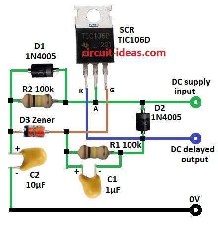
Parts List:
| Component | Value/Type | Quantity |
|---|---|---|
| Resistors | 100k 1/4 watt | 2 |
| Capacitors | Tantalum 1µF 35V | 1 |
| Tantalum 10µF 35V | 1 | |
| Semiconductors | SCR 4A TIC106D | 1 |
| Diode 1N4005 | 2 | |
| Zener Diode rating should be half the input supply voltage. | 1 |
Circuit working is simple as it uses SCR switch to control output.
When power is ON, C2 charge through R2.
Charge time decide when SCR is ON.
At first SCR is OFF with no output.
When C2 is full enough then small current goes through D3, R2 and make SCR ON.
SCR ON means power goes to output.
C1 and R1 keep steady and stop false trigger.
D1 and D2 block unwanted current.
Formulas with Calculations:
Delay time T is mainly from C2 and R2.
Formula: T = R2 × C2 × ln(Vth / (Vcc – Vth))
where,
- Vth is SCR trigger 0.7V
- Vcc is supply R2 is 100k
- C2 is 10µF
- ln is natural log.
Example: Vcc = 12V
T = 2.33 sec delay.
How to Build:
To build a Simple Time Delay Circuit for DC Power following steps are required to be followed:
- Gather all parts from circuit diagram.
- Connect D1 and R2 in parallel.
- Connect D3 cathode to one end of R2 and D1.
- Connect D3 anode to SCR GATE pin.
- Connect SCR anode to supply input.
- Connect SCR anode also to R2 and D1 and other end connect to D2 cathode.
Connect SCR K pin to delayed output. - Connect R1 and C1 in parallel.
- Connect one end of R1 and C1 between D3 anode SCR GATE and other end connect to SCR K pin.
- Connect C2 one end to D3 anode and other end connect to GND.
Conclusion:
This Simple Time Delay Circuit for DC Power uses to turn devices one by one.
It changes delay by connecting different R and C value.
SCR give steady and reliable switching.
Leave a Reply