Logic AND gate is a basic digital logic gate.
It gives high output only when both inputs are high.
In this Logic AND Gate Circuit using Transistors is easy to make.
This is a simple example of transistor logic gate.
Truth Table for Logic AND Gate:
| Input A | Input B | Output Y |
|---|---|---|
| 0 (LOW) | 0 (LOW) | 0 (LOW) |
| 0 (LOW) | 1 (HIGH) | 0 (LOW) |
| 1 (HIGH) | 0 (LOW) | 0 (LOW) |
| 1 (HIGH) | 1 (HIGH) | 1 (HIGH) |
Output Y becomes HIGH only when both inputs A and B are HIGH.
If any one input is LOW then output remains LOW.
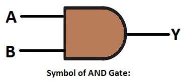
Symbol of Logic AND Gate:
Circuit Working:
Parts List:
| Component | Value | Quantity |
|---|---|---|
| Resistors | 1k | 1 |
| 10k | 2 | |
| Semiconductors | Transistors (NPN) BC547 | 2 |
| Power Supply +5V DC | 1 |
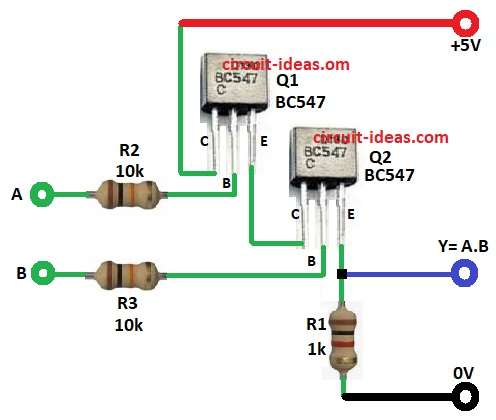
The circuit has two inputs A and B.
When both inputs are logic 1 (high) then both transistors Q1 and Q2 conduct.
Then current flows from +5V to ground through both the transistors.
This makes the output Y low (logic 0) at emitter of Q2.
When any input is low then one transistor cuts off and no current flows,
and the output Y stays high (logic 1).
So output Y = A × B (AND gate function).
Formulas with Calculations:
Circuit Formula with Calculation are shown below:
Output logic follows AND rule: Y = A × B.
When A = 1 and B = 1 then
Both Q1 and Q2 ON then current flows with Y = 1.
When A = 0 or B = 0 then
Any transistor is OFF with no current path then Y = 0.
To find base current:
Ib = (Vin – Vbe) / Rb
Assume Vbe = 0.7V and Vin = 5V, Rb = 10kΩ
Ib = (5 – 0.7) / 10000 = 0.00043A = 0.43mA
Collector current:
Ic = β × Ib
Assume β = 100
Ic = 100 × 0.43mA = 43mA
This is enough to drive small loads.
How to Build:
To build a Logic AND Gate Circuit using Transistors following are the connection steps:
- Gather all the circuit parts as shown in above diagram.
Transistor Q1 BC547 connection:
- Pin 1 collector connected to +5V through resistor R2.
- Pin 2 base connected to input A through 10k R2 resistor.
- Pin 3 emitter connected to collector of Q2.
Transistor Q2 BC547 connection:
- Pin 1 collector connected to emitter of Q1.
- Pin 2 base connected to input B through 10k R3 resistor.
- Pin 3 emitter connected to ground through resistor R1 1k.
- Output Y = A.B is connected between emitter of transistor Q2 and resistor R1
Conclusion:
Logic AND Gate Circuit using Transistors is simple and easy to build.
It helps to understand digital logic using analog components.
Only when both inputs are high, output becomes high.
Useful for logic control and basic learning of transistor switching.
Leave a Reply