To begin with, Analog circuits are very important part of electronics because these circuits work with continuous signal and voltage can change smoothly from one value to another value.
Many electronic devices like radio, amplifier, sensor and power supply are using analog circuits for their operation.
By learning basic of analog circuits, beginners can understand how electronic parts like resistor, capacitor, diode and transistor work together in a circuit.
Also, it helps to understand signal processing, amplification and control circuits; in addition, learning analog electronics gives a strong base for making many useful and interesting electronics projects.
Working of Analog Circuit:
Circuit Parts used in for Analog Circuits:
| Components | Functions |
|---|---|
| Resistor (R) | Controls current and voltage levels in the circuit. |
| Capacitor (C) | Stores electrical charge and filters unwanted noise. |
| Transistor | Works as an amplifier or a switch. |
| Operational Amplifier (Op-Amp) | Boosts weak input signals to higher levels. |
| Diode | Allows current to flow in one direction only. |
| Power Supply | Provides the required voltage and power to run the circuit. |
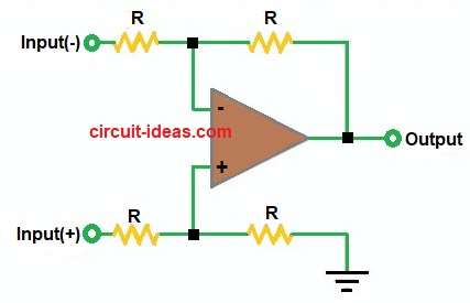
In the above diagram the op-amp takes two inputs with positive and negative, then resistors balance both inputs and output depends on difference between inputs.
If the positive (+) input becomes larger, the circuit produces a positive output and if the negative (–) input becomes larger, the circuit produces a negative output.
Therefore, the circuit amplifies the difference between the two inputs and acts as a differential amplifier.
Two Main Types of Analog Circuits are:
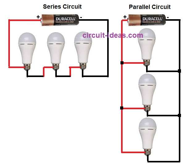
Series Circuit:
- Current is same through all parts and if one part breaks then all stop working.
Parallel Circuit:
- Voltage is same across all parts and if one part fails then others still work.
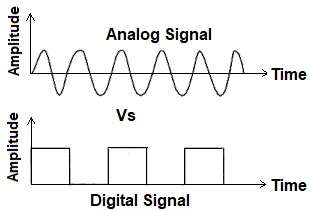
Difference Between Analog Signal and Digital Signal:
| Feature | Analog Signal | Digital Signal |
|---|---|---|
| Form | Continuous wave | Discrete steps (0 and 1) |
| Value | Infinite values | Limited values |
| Noise | Affected by noise | Less noise |
| Example | Sound, temperature | Computer data, binary code |
Types of Analog Circuit:
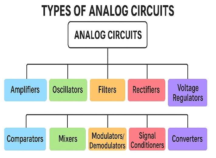
Below is the diagram chart showing for a family tree of analog circuits:
| Categories | Functions | Examples |
|---|---|---|
| Amplifiers | Increases the strength (amplitude) of a weak signal. | Op-amp amplifier, transistor amplifier, instrumentation amplifier |
| Oscillators | Generate continuous waveforms (sine, square and triangular). | RC oscillator, LC oscillator, Wien bridge oscillator |
| Filters | Remove unwanted frequencies from a signal. | Low-pass, High-pass, Band-pass, Notch filter |
| Rectifiers | Convert AC to DC current. | Half-wave rectifier, Full-wave rectifier, Bridge rectifier |
| Voltage Regulators | Maintain constant output voltage. | Zener regulator, IC 7805 regulator |
| Comparators | Compare two voltages and output a digital-like signal. | Op-amp comparator, zero-crossing detector |
| Mixers | Combine multiple signals into one. | Audio mixer, RF mixer |
| Modulators/Demodulators | Modify or recover signal for communication. | AM, FM, PM circuits |
| Signal Conditioners | Prepare sensor signals for processing. | Level shifters, filters, amplifiers |
| Converters | Change one signal type to another. | Analog-to-digital (ADC), Digital-to-analog (DAC) |
Applications of Analog Circuits:
- Audio amplifiers
- Radio and TV circuits
- Sensor signal processing
- Communication systems
- Measurement instruments
Advantages of Analog Circuits:
- Simple and easy to understand for basic applications.
- Good for processing real-world signals like sound, temperature and light.
- Produces smooth and continuous output signals.
- Usually needs fewer components for simple circuits.
- Works well in audio and sensor applications.
Disadvantages of Analog Circuits:
- Signals can affect by electrical noise.
- Accuracy is lower than digital circuits.
- Difficult to store and process information.
- Circuit performance may change because of temperature and component aging.
- Troubleshooting and modification can be more difficult in complex analog circuits.
Conclusion:
To conclude, analog circuits play a very important role in electronics, and many electronic devices use them every day; also by learning the basics of analog circuits, beginners can understand how different electronic components work together and how circuits control and amplify signals.
Finally, this knowledge gives a good foundation for learning more advanced electronics and making many useful electronic projects in the future.

Leave a Reply