Arduino Line Follower Robot Circuit uses sensors and motors.
IR sensors look at floor all time and they find black line and white area, Arduino read these sensor signals and then it tell motor driver what to do.
Motor driver control wheels speed and direction and then robot follow black line by itself.
Arduino Code:
int leftIR = 2;
int rightIR = 3;
int in1 = 5;
int in2 = 6;
int in3 = 9;
int in4 = 10;

void setup() {
  pinMode(leftIR, INPUT);
  pinMode(rightIR, INPUT);
  pinMode(in1, OUTPUT);
  pinMode(in2, OUTPUT);
  pinMode(in3, OUTPUT);
  pinMode(in4, OUTPUT);
}

void loop() {
  int leftVal = digitalRead(leftIR);
  int rightVal = digitalRead(rightIR);

  if (leftVal == 1 && rightVal == 1) {
    forward();
  }
  else if (leftVal == 0 && rightVal == 1) {
    leftTurn();
  }
  else if (leftVal == 1 && rightVal == 0) {
    rightTurn();
  }
  else {
    stopMotor();
  }
}

void forward() {
  digitalWrite(in1, HIGH);
  digitalWrite(in2, LOW);
  digitalWrite(in3, HIGH);
  digitalWrite(in4, LOW);
}

void leftTurn() {
  digitalWrite(in1, LOW);
  digitalWrite(in2, LOW);
  digitalWrite(in3, HIGH);
  digitalWrite(in4, LOW);
}

void rightTurn() {
  digitalWrite(in1, HIGH);
  digitalWrite(in2, LOW);
  digitalWrite(in3, LOW);
  digitalWrite(in4, LOW);
}

void stopMotor() {
  digitalWrite(in1, LOW);
  digitalWrite(in2, LOW);
  digitalWrite(in3, LOW);
  digitalWrite(in4, LOW);
}
Code Explanation:
- LeftIR and RightIR are pins are for IR sensors.
- MotorLeft and MotorRight pins control the L298N driver.
- The forward function makes both motors move forward.
- LeftTurn and RightTurn spin motors in opposite ways to turn the robot.
- IR sensors give 1 on white and 0 on the black line.
- Arduino reads the sensors and decides the direction.
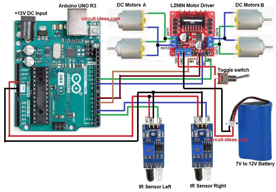
Circuit Diagram:
Parts List:
| Components | Quantity |
|---|---|
| Arduino UNO R3 | 1 |
| L298N Motor Driver | 1 |
| IR Sensor | 2 |
| DC Motors with Wheels | 4 |
| 7V to 12V Battery | 1 |
| SPST Toggle switch | 1 |
| Robot Chassis | 1 |
How to Build:
To build a Arduino Line Follower Robot Circuit follow the below steps:
- First, assemble all parts like in circuit diagram.
- Next, left IR sensor output go to Arduino pin 2.
- Then right IR sensor output go to Arduino pin 3.
- Also, both IR sensor VCC go to Arduino 5V and both sensor GND go to Arduino GND.
- Now L298N IN1 go to Arduino pin 5 and L298N IN2 go to Arduino pin 6.
- Further, L298N IN3 go to Arduino pin 9 and L298N IN4 go to Arduino pin 10.
- After that, motor A wires go to OUT1 and OUT2 and motor B wires go to OUT3 and OUT4.
- Finally, L298N 12V pin go to battery positive, battery negative go to GND and then connect switch to the positive of battery.
Conclusion:
To conclude, this is simple Arduino Line Follower Robot Circuit which is good for learning Arduino basics.
Here, the IR sensors see the line and then Arduino read signals and run motors with L298N driver; then robot move and follow path by itself.
Also, this circuit is easy to make and is good for beginners and school project.

Leave a Reply