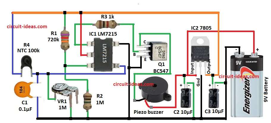
In winter season, water and surrounding air can go below zero degree.
At that time it is useful to have a small alarm which tells us when temperature goes near freezing point.
This Buzzer Alert at 0°C Indicator Circuit uses thermistor sensor, one op-amp IC and a piezo buzzer to make sound alarm when temperature is near 0°C.
This circuit is very small and runs from battery.
Circuit Working:

Parts List:
| Component | Value | Quantity |
|---|---|---|
| Resistors | 720k 1/4 watt | 1 |
| 1M 1/4 watt | 1 | |
| 1k 1/4 watt | 1 | |
| Preset 1M | 1 | |
| Thermistor NTC 100k | 1 | |
| Capacitors | Ceramic 0.1µF | 1 |
| Electrolytic 10µF 25V | 2 | |
| Semiconductors | IC LM7215 | 1 |
| IC 7805 | 1 | |
| Transistor BC547 | 1 | |
| Piezo buzzer 9V | 1 | |
| Battery 9V | 1 |
This small circuit give alarm when temperature goes below zero.
The main sensor is thermistor R4 and this thermistor is a resistor whose value changes with temperature
Op-amp LM7215 compare two voltages one from reference and one from thermistor.
Reference go to pin 3 and thermistor network goes to pin 4.
When temperature is less than zero then pin3 voltage goes bigger than pin 4 and output of op-amp goes high.
This switch ON transistor Q1 and buzzer makes sound.
So alarm rings when temperature is near zero degree.
For power supply we used IC 7805 which make 5V from 9V battery.
Formulas:
Voltage divider formula is:
Vout = Vin × (R2 / (R1 + R2))
here,
- Vin is supply 5V.
For thermistor divider the resistance R changes with temperature.
The resistance of NTC thermistor is given by formula:
R(T) = R0 × exp[ B × (1/T – 1/T0) ]
where,
- R0 is resistance at reference temperature T0
- B is the constant given by manufacturer
- T is the actual temperature in Kelvin
By adjusting resistor values R1, R2, R3 we set reference so comparator switches at about 0°C.
Resistor R3 is simply base resistor for Q1.
Value 1k resistor is enough to limit base current and drive a buzzer.
How to Build:
To build a Buzzer Alert at 0°C Indicator Circuit following are the connections steps we need to follow:
- First collect all parts same like circuit diagram.
IC1 LM7215 Connection:
- Pin1 is output and it goes to base of transistor Q1 through resistor R3.
- Pin2 is +V input connect to +5V.
- Pin3 is non-inverting input and connect to divider R2 and VR1.
- Pin4 is inverting input connect to junction of thermistor R4, VR1 and capacitor C1.
- Pin5 V- connect to ground.
Transistor Q1 BC547 Connection:
- Base connect at R3.
- Collector connect to one side of buzzer.
- Other side of buzzer go to +9V.
- Emitter go to ground.
Power section IC 7805 Connection:
- Pin1 input goes to +9V battery and negative battery go to ground.
- Pin2 GND connects to ground.
- Pin3 output connects to +5V with Capacitor C3 positive to output and capacitor negative to ground.
Conclusion:
This Buzzer Alert at 0°C Indicator Circuit is simple and cheap.
It uses one thermistor sensor, comparator IC, transistor and buzzer.
When temperature falls near zero buzzer rings.
It can be used in refrigerators, cold storage or outside in winter.
By changing resistor values the alarm point can be shifted to other temperatures also.