It is good to know How to Increase Voltage Output of 7812,7805 ICs chip but not a really good idea.
These chip are made to give fixed voltage like 7812 give 12V and 7805 give 5V.
Better way is this:
If we want other voltage just buy other voltage regulator chip.
There are many different chip out there for what we need.
If we really want then use 7812 or 7805 we can make special circuit with extra parts to increase the voltage.
But this is hard to do which is not good for beginner person.
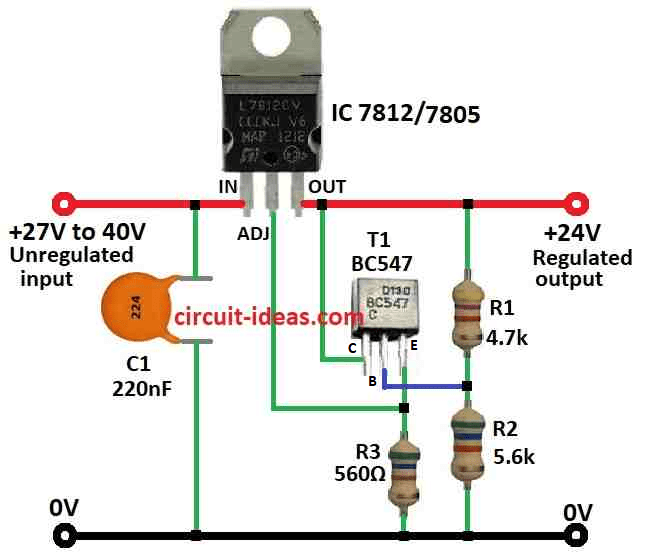
Circuit Working:
Parts List:
| Category | Component | Quantity |
|---|---|---|
| Resistors | 4.7k 1/4 watt | 1 |
| 5.6k 1/4 watt | 1 | |
| 560Ω 1/4 watt | 1 | |
| Capacitors | Ceramic 220nF | 1 |
| Semiconductors | IC 7812 or 7805 | 1 |
| Transistor BC547 | 1 |
Sometimes we need to change voltage regulator IC to give more voltage than normal.
One way is to connect common pin to middle point of two resistors like voltage divider.
But this way there is a problem small current around 10mA always connect from common pin to ground.
This small current is not always the same so output voltage is not stable.
If we use small resistor values maybe it will help.
But then more heat will be added and circuit will not work so good.
This circuit here uses transistor T1 to fix problem and T1 makes low resistance at common pin using emitter follower.
Now voltage divider move to different part with big resistors so there is no problem with heat.
R3 value is not too important but must be small enough so T1 does not turn OFF even with big quiescent current.
Formula:
This formula uses simple transistor setup.
The voltage at transistor emitter is around 2 volt drop and at input voltage Vin, all these change the output voltage (Vout).
How to find output voltage:
Vout = Vin – 2 + (Transistor Emitter Voltage)
where:
- Vin is the voltage we give to the circuit.
- 2 is voltage drop inside the IC.
- Transistor Emitter Voltage is the voltage at transistor emitter pin.
How to Build:
Below are the steps, how to build a Increase Voltage Output of 7812,7805 ICs:
Circuit Diagram:
- First connect input voltage to input pin of voltage regulator IC.
- Then connect output pin of regulator to the load like device we want to power.
- Connect ground pin of regulator to ground of input voltage and ground of load.
Adding the Transistor T1:
- Connect transistor emitter to ground.
- Connect transistor collector to output pin of voltage regulator.
- Connect base of transistor to middle point of two resistors R1 and R2.
Adjusting Divider Network:
- Use resistor R1 and R2 to make voltage divider.
- Connect common pin of voltage regulator IC to middle of R1 and R2.
Adding Capacitors:
- Put capacitor C1 between input pin and ground pin of voltage regulator for clean input voltage.
Testing and Fine Tuning:
- Turn ON the power and check output voltage.
- Use potentiometer instead of R2 if we want to fine tune voltage.
Adjusting Component Values:
- If output voltage is not correct or not stable then try changing values of resistors or capacitor.
Finalizing the Circuit:
- When output voltage is good we can solder all parts on PCB or protoboard to make it permanent.
Note:
- Be careful when working with electricity and always check polarity of components and follow safety rules.
Conclusion:
How to Increase Voltage Output of 7812,7805 ICs we can use voltage boosting circuit like voltage multiplier.
This help to get higher voltage than what regulator normally give.
But it is very important to use right components for the voltage we want and also test the circuit carefully to be sure it work properly.
Leave a Reply