Logic OR Gate Circuit using Transistors is simple digital logic gate, it give HIGH output if any input is HIGH.
We can make Logic OR Gate using two NPN transistor like BC547 and it also uses small current and is easy to build.
Truth Table for Logic OR Gate:
| Input A | Input B | Output Y |
|---|---|---|
| 0 | 0 | 0 |
| 0 | 1 | 1 |
| 1 | 0 | 1 |
| 1 | 1 | 1 |
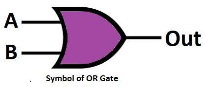
Symbol of Logic OR Gate:
Circuit Working:
Parts List:
| Components | Values | Quantity |
|---|---|---|
| Resistors | 1k | 1 |
| 10k | 2 | |
| Semiconductors | Transistors (NPN) BC547 | 2 |
| Power Supply +5V DC | 1 |
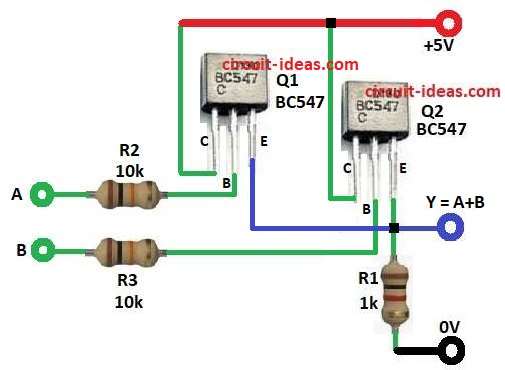
The above circuit uses two BC547 NPN transistor and each transistor is small switch.
Input A go to base of Q1 via 10k R2 and input B go to base of Q2 via 10k R3.
Then both emitter join together and also join emitter to ground via 1k R1.
After that, collector go to +5V and output Y take from emitter join.
A = 0, B = 0 then no base current and both are OFF with Y = 0.
Any input is HIGH then that transistor is ON and current flow R1 with Y = 1 and both input are HIGH then both are ON with Y = 1.
Hence, this circuit work as OR Gate.
Formulas:
Below are the formulas for Logic OR Gate Circuit using Transistors:
Base current Ib = (Vin − Vbe) / Rb
Emitter current Ie = Ib × (1 + hFE)
Output voltage Y = Ie × R1
How to Build:
To build a Logic OR Gate Circuit using Transistors follow the connection steps:
- First, assemble all parts like circuit diagram.
- Next, base of Q1 connect to input A via 10k R2, and base of Q2 connect to input B via 10k R3.
- Then collectors of both transistor connect to +5V and emitters join together and connect to 1k R1.
- Also, other end of R1 connect to ground and finally, output Y take from emitter join.
Conclusion:
Overall, this simple circuit acts as an Logic OR Gate using two NPN transistors, also it shows digital logic using basic parts.
In addition , it helps to understand logic gate working by transistor switching.