Need a clean negative voltage for your project? Then this 9V negative power supply circuit is a perfect solution which provides low ripple output and stable performance, making it suitable for many DIY electronics applications.
This circuit is designed to produce a smooth 9V negative DC supply from AC input which at first, steps down the voltage then rectifies and filters it and as a result, the output becomes clean and stable for sensitive electronic circuits.
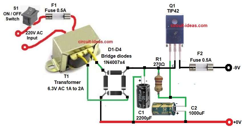
The Low Ripple -9V Regulated Power Supply Circuit uses a step-down transformer, bridge rectifier diodes, filter capacitors and a TIP42 transistor for better output filtering.
Therefore, this circuit is useful for op-amp circuits, audio circuits and electronic projects that need negative DC supply.
Circuit Working:
Parts List:
| Components | Values | Quantity |
|---|---|---|
| Resistor | 270Ω 1/4 watt | 1 |
| Capacitors | Electrolytic 1000uF 25V, 2200µF 25V | 1 each |
| Semiconductors | Transformer primary 220V AC ,secondary 6.3V AC 1A to 2A | 1 |
| Fuse 0.5A | 2 | |
| ON/OFF Switch | 1 | |
| Transistor TIP42 PNP | 1 | |
| Bridge Diodes 1N4007 | 4 | |
| Output Power Supply 9V DC Negative | 1 |
First, AC mains supply enters through switch S1 and fuse F1, the switch is used to turn the circuit ON and OFF and the fuse protects the circuit from over current.
Next, transformer T1 steps down 220V AC to 6.3V AC and then this low AC voltage goes to the bridge rectifier made using D1 to D4.
After that, the bridge rectifier converts AC into pulsating DC and since this is a negative power supply circuit, the output terminal becomes negative with respect to ground.
Still, ground works like positive reference point, but it is still called ground (0V).
Then capacitor C1 filters the pulsating DC as it removes most of the ripple and because of this, the output becomes more smooth.
After that, resistor R1 gives bias current to transistor Q1 and this transistor works like a pass transistor which improves voltage stability and also helps reduce ripple more.
Finally, capacitor C2 gives final smoothing at output side and so the circuit gives low ripple negative DC output close to -9V.
How to Build:
To build a Low Ripple -9V Regulated Power Supply Circuit follow the below connection steps:
- First, the circuit starts by collecting all the parts as in diagram above.
- Next, take transformer T1 with primary one side connect fuse F1 and switch S1 for AC live.
- Connect other side to AC neutral.
- Next, take secondary side and connect both the sides to bridge rectifier AC input.
- Then take diodes D1 to D4 and connect in bridge form as in diagram.
- After that take, capacitor C1 with negative pin connect to negative DC line and positive pin connect to ground 0V.
- Then take resistor R1 and one side connect to negative rectified line and other side of resistor connect to base of TIP42 and negative of capacitor C2.
- Next, take TIP42 Transistor connect base pin between R1 resistor one end and capacitor C2 negative, collector pin connect to rectifier negative line and emitter pin goes to output terminal of -9V through fuse F2.
- Lastly, capacitor C2 negative pin connect between base of transistor Q1 and resistor R1 one end and positive pin goes to ground 0V.
Conclusion:
This Low Ripple -9V Regulated Power Supply Circuit gives smooth and low ripple DC output.
Moreover, the TIP42 transistor and filter capacitors improve voltage quality and reduce noise.
Therefore, this circuit is a good choice for electronic circuits that need a stable negative voltage supply and also it is easy to build using common components.
Leave a Reply