7-segment display show numbers 0 to 9.
Sometimes it show small letters.
LED make it bright and famous.
Now LCD are also come in use.
Things like microwave, calculator, washing machine, radio, digital clock use it for numbers.
Next we see 7-segment pins for better understanding.
Diagram with Pinouts:

Seven-segment display have seven light parts.
Parts join to make numbers and letters.
Different parts on, show different characters.
Binary data can show on these parts.
LED is P-N diode.
It make light but does not heat like normal diode.
It does not give light by itself.
LED or LCD show numbers or letters needed.
Pin Configuration:
Seven Segment Display mostly have 10 pins and one pin is common.
Below table show pin setup:
| Pin | Segment | Function |
|---|---|---|
| 1 | E | Controls segment ‘E’ |
| 2 | D | Controls segment ‘D’ |
| 3 | Common | Common Cathode/Anode |
| 4 | C | Controls segment ‘C’ |
| 5 | DP | Controls the decimal point (optional) |
| 6 | B | Controls segment ‘B’ |
| 7 | A | Controls segment ‘A’ |
| 8 | Common | Common Cathode/Anode |
| 9 | F | Controls segment ‘F’ |
| 10 | G | Controls segment ‘G’ |
Common Anode 7-Segment Display:
All negative pins anode of 8 LEDs join together and positive pins stay separate.
Common Cathode 7-Segment Display:
All positive pins cathode of 8 LEDs join together and negative pins stay separate.
How it Works:
Each segment has a small LED.
It turn ON some segments to show numbers.
LEDs glow when its forward-biased.
Brightness depends on forward current.
Driver gives enough current to light all segments fully.
Example to show 8 it light up all 7 segments from A to G
Example it show numbers on Common Cathode SSD.
Decimal Digit Representation (CC):
| Digit | A | B | C | D | E | F | G |
| 0 | 1 | 1 | 1 | 1 | 1 | 1 | 0 |
| 1 | 0 | 1 | 1 | 0 | 0 | 0 | 0 |
| 2 | 1 | 1 | 0 | 1 | 1 | 0 | 1 |
| 3 | 1 | 1 | 1 | 1 | 0 | 0 | 1 |
| 4 | 0 | 1 | 1 | 0 | 0 | 1 | 1 |
| 5 | 1 | 0 | 1 | 1 | 0 | 1 | 1 |
| 6 | 1 | 0 | 1 | 1 | 1 | 1 | 1 |
| 7 | 1 | 1 | 1 | 0 | 0 | 0 | 0 |
| 8 | 1 | 1 | 1 | 1 | 1 | 1 | 1 |
| 9 | 1 | 1 | 1 | 1 | 0 | 1 | 1 |
For Common Anode the logic is opposite and gives 0 (LOW) to turn ON the segment.
Interfacing a 7-segment display to Arduino UNO:
Below we have connected a 7-segment display to Arduino UNO for example:
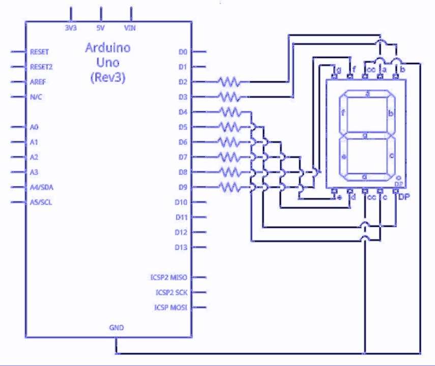
We connect 7-segment display to Arduino UNO.
Each segment has one pin.
Arduino controls which segments turns ON.
When turn ON some segments shows number .
We use wires to join display pins to Arduino pins.
Power Arduino display which shows numbers.
How to Build:
Seven Segment Display Circuit (SSD) made up of:
- Outer body is made of plastic or epoxy
- LEDs are 7 small in 8 shape
- Wiring is of common cathode or anode inside
- Metal Pins are used to connect with circuits
Formulas and Calculations:
To keep SSD safe use right resistor with each LED.
Use Ohms Law to the find resistor:
Formula:
R = (Supply Voltage – LED Forward Voltage) / Desired Current
where,
- R is the resistor in ohms Ω.
- Supply Voltage is from Arduino or battery.
- LED Forward Voltage is drop across LED when ON.
- Desired Current is current through LED in amperes.
Conclusion:
This project for Seven Segment Display Circuit is simple and with low cost.
Seven segment display show numbers clearly.
It is easy to connect with IC or Arduino.
Circuit is useful in calculator, clock, counter and digital meter.
Leave a Reply