Simple 1.5V White LED Driver Circuit is like power translator.
It takes power from battery and changes it to right voltage and current for LED.
This helps LED shine bright and safe.
Without driver LED may be dim or may burn.
Circuit Working:
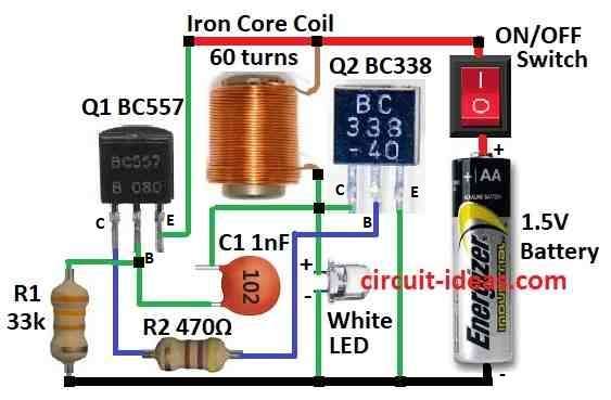
Parts List:
| Category | Description | Quantity |
|---|---|---|
| Resistors | 33k, 470Ω (1/4 watt each) | 1 each |
| Capacitor | Ceramic 1nF | 1 |
| Semiconductors | Transistors BC557, BC338 | 1 each |
| White LED 5mm, 20mA | 1 | |
| Inductor Iron core coil slug (2.6mm diameter, 6mm long, 0.25mm wire) | 1 | |
| ON/OFF Switch | 1 | |
| 1.5V Battery | 1 |
This is simple 1.5V white LED driver circuit.
It use transistor to control current to LED.
This one is better than basic driver.
It use special design to power super bright LED.
When switch ON battery sends current through R1.
R1 gives power to base of transistor Q1 BC557 so Q1 turns ON.
When Q1 is ON lets current flow from collector to emitter and through coil and LED.
C1 1nF capacitor makes positive feedback.
Voltage goes up and transistor turns more ON signal gets stronger.
Then it reaches top and transistors turns OFF.
This ON-OFF cycle makes oscillation to run LED.
Circuit uses coil with 60 turns.
Coil is on ferrite core with 2.6mm wide, 6mm long and wire is 0.25mm.
Ferrite helps make circuit more efficient.
When current flows coil stores energy.
When switch is OFF then coil gives energy burst to LED.
This helps LED stay bright for short time.
This design uses 1nF capacitor and two transistors for feedback.
So it makes oscillation in smart way and not just for coil.
Note:
If no ferrite core then we can use machine screw or brass ferrule to make coil.
Formulas:
Ohms Law Formula:
Use this to find resistor value in 1.5V White LED Driver:
R = V / I
- R is the resistance in ohms Ω
- V is the voltage in volts
- I is the current in amps A
Use this formula to find value of resistor R1.
How to Build:
To build a Simple 1.5V White LED Driver Circuit follow the connections steps mentioned below:
- Connect collector of Q1 to base of Q2 through R2.
- Connect base of Q1 to one side of capacitor C1.
- Connect emitter of Q1 to positive supply through coil with iron core.
- Connect collector of Q2 to other side of capacitor C1.
- Connect base of Q2 to collector of Q1.
- Connect emitter of Q2 to ground.
- Connect white LED from collector of Q2 to ground.
- Connect ON/OFF switch to positive of 1.5V battery.
Safety Note:
- While making circuit be careful and check all parts and values.
- Build a clean and safe circuit to avoid damage.
Conclusion:
This Simple 1.5V White LED Driver Circuit shows how current changes with different coil core materials.
Good core means better efficiency and brightness with same power.