This article discuss how to make 100 Watt Amplifier Circuit using IC LM12.
No need of many parts or costly wires.
Just follow some easy step and we can get nice and powerful sound.
This 100 watt amplifier is small and is build easy and is good for many uses.
It gives strong 100 watt sound to boost audio signal with LM12 IC.
Circuit Working:
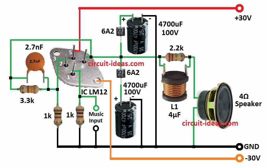
Parts List:
| Component | Quantity |
|---|---|
| Resistors | |
| 3.3k 1/4 watt | 1 |
| 2.2k 1/4 watt | 1 |
| 1k 1/4 watt | 2 |
| Capacitors | |
| Ceramic 2.7nF | 1 |
| Ceramic 100nF | 2 |
| Electrolytic 4700μF 100V | 6 |
| Semiconductors | |
| Diodes 6A2 | 2 |
| Diodes 6A4 | 4 |
| IC LM12 | 1 |
| Transformer 24V-0-24V 5 Amp | 1 |
| Inductor L1 4μF | 1 |
| Speaker 4Ω | 1 |
Using LM12CLK IC to make simple 100 watt amplifier is easy and works good.
This IC is very strong and can give power up to 150W if low speaker ohm is like 2 ohms.
But this circuit best work with 4 ohm speaker and it gives stable and safe power to around 100W RMS.
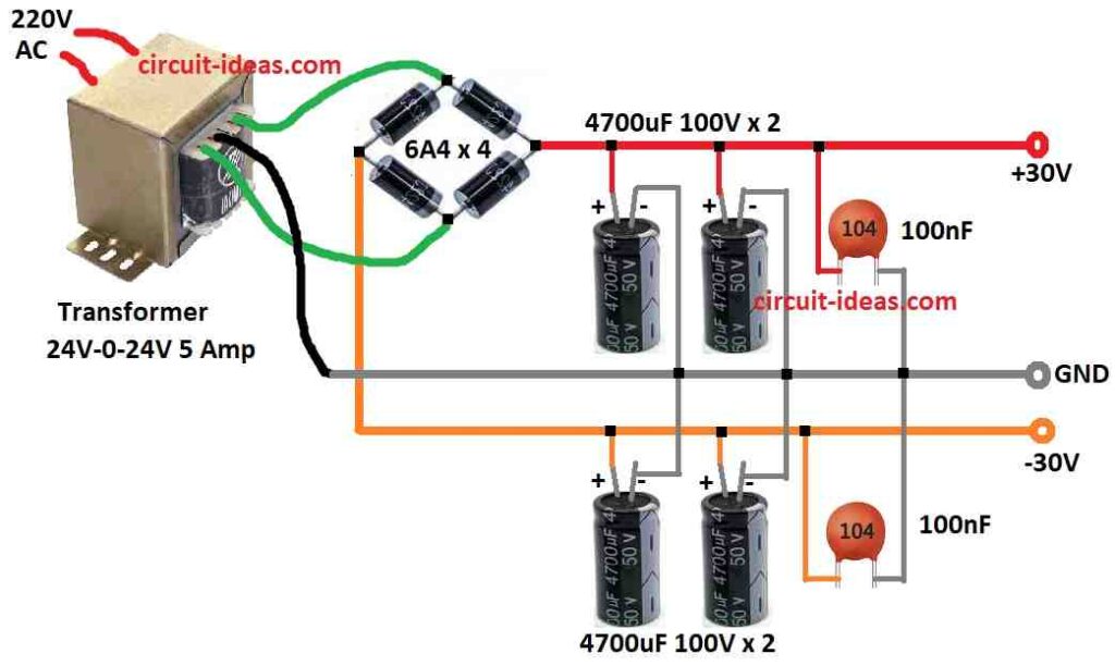
Transformer need to give 24V + 24V AC with 5A for mono or 10A for stereo use.
Better to use metal bridge rectifier with heat sink and not 4 diode bridge.
For output coil L make 14 turns and use 18 wire with no core and 1 inch wide.
How far coil turns from each other does not matter much.
Use exact 1k ohm resistor and at least 2W power for best result.
Electrolytic capacitors must be 50V or 63V rated.
All parts work together to make strong and nice sound.
This project is small but gives powerful and clear sound and makes sound system better.
This circuit is easy to build and we can enjoy great sound after.
Next step is to make our own 100W amp using one IC only.
Formula:
This formula show how one type of amplifier circuit work where voltage gain (Av) is in the formula:
Av = 1 + R3 / R2
here:
- Av is voltage gain of amplifier.
- If amplifier makes signal stronger then Av is more than 1.
- R3 is feedback resistor which goes between op-amp output and inverting input.
- R2 is gain resistor which goes between inverting input and ground.
Understanding non-inverting op-amp:
For non-inverting op-amp gain formula also is:
Av = 1 + R3 / R2
This mean voltage gain depend on R3 divide by R2.
If R3 is big and R2 is small then gain is high.
Important things to know:
This formula is only for non-inverting op-amp.
Other types like inverting op-amp use different formula.
This formula thinks of op-amp which is perfect with infinite gain, infinite input impedance but in actual circuit it is not perfect.
Real gain maybe different because of real parts and limits.
To get wanted gain choose right R2 and R3 values.
That way we can build amplifier with needed voltage gain.
How to Build:
For building a 100 Watt Amplifier Circuit using IC LM12 involves several connections and assembling process:
First Safety:
- Be sure we have right tools and clean safe work area.
- Check all parts again and follow safety rules.
Power Source:
- Connect transformer to give power to circuit.
- Use 5A current for mono and 10A current for stereo.
- Better use metal bridge rectifier with heat sink and not for four diodes.
Output Coil (L):
- Make coil L by winding 14 turns of 18 wire on 1 inch round with no core.
- Exact space is between turns which is not important.
Use IC LM12:
- Connect circuit board with LM12 IC.
- See datasheet or pinout for correct connection.
- Connect 50V or 63V electrolytic capacitors and exact 1k 2W resistors to right LM12 pins.
Speaker Connection:
- Connect 4 ohm speaker to amplifier output.
- Check all connections two times.
- Turn ON circuit slowly and watch if anything goes wrong or strange things happen.
- Use tools like multimeter or oscilloscope to check signal is good.
Conclusion:
With LM12 IC we can make 100W amplifier with cheap parts.
This 100 Watt Amplifier Circuit using IC LM12 give strong and clear sound and is good for music lovers who want better sound system.
References:
Application Note 446 A 150W IC Op Amp Simplifies Design of Power Circuits