FM (Frequency Modulation) is a common way to send audio by radio signals, also many people like making FM transmitters with Arduino because DIY electronics is getting popular.
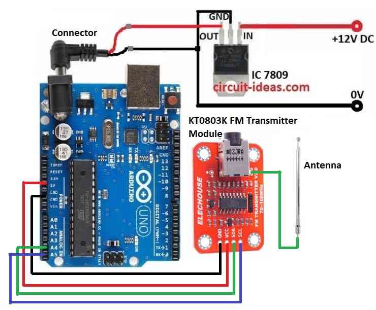
In this project for Simple Arduino FM Transmitter Circuit we have used Arduino Uno, KT0803K FM module, 7809 voltage regulator and simple antenna to make FM transmitter.
Furthermore, this circuit is fun and helps us learn how radio works.
Arduino Code:
#include <Wire.h>

#define SCL_PIN A5 // Define SCL pin
#define SDA_PIN A4 // Define SDA pin

void setup() {
  Serial.begin(9600);
  Wire.begin(SDA_PIN, SCL_PIN); // Initialize I2C communication with specific pins

  // Example of sending a command to the KT0803K
  // Replace with actual commands as per your module's datasheet
  Wire.beginTransmission(0xXX); // Replace 0xXX with the KT0803K I2C address
  Wire.write(0x01); // Example command (modify as needed)
  Wire.endTransmission();
}

void loop() {
  // Add your code to handle audio input and control the KT0803K
}
Circuit Working:
Parts List:
| Components | Quantity |
|---|---|
| Arduino Uno | 1 |
| KT0803K FM Transmitter Module | 1 |
| IC 7809 Voltage Regulator | 1 |
| Antenna | 1 |
In this project, IC 7809 gives stable 9V power to Arduino and KT0803K and Arduino Uno works like brain microcontroller and it controls the transmission.
Then Arduino sends data to KT0803K module and KT0803K is main part of transmitter and it changes data into FM radio waves.
Module has pins for antenna, power and data input.
Antenna sends out FM radio waves and we can change antenna length to get better signal and longer range.
How to Build:
To build a Simple Arduino FM Transmitter Circuit follow the below mentioned steps for connections:
- First, collect all parts like in circuit diagram above.
- Next, use IC 7809 to give steady 9V power to Arduino, see the circuit diagram.
- Then connect KT0803K GND pin to Arduino GND.
- After that, connect KT0803K VCC pin to Arduino 5V.
- Now, connect KT0803K SDA pin to Arduino A4.
- Also, connect KT0803K SCL pin to Arduino A5 and then connect antenna to KT0803K antenna pin as per the circuit diagram.
Conclusion:
To conclude, making Simple Arduino FM Transmitter Circuit with KT0803K FM Transmitter Module is fun and good to learn about radio basics.
Also, it easy to build but we can explore more like better sound and how FM works.
Finally, check your country rules before using FM transmission and then enjoy sending your own audio!
Leave a Reply