This special Automatic Parking Light Switch Circuit makes car parking lights turn ON by itself and it also helps to look outside to see how bright it is.
Here, one light sensor is like LDR thing which check the light outside and if outside it become dark, more dark than set level then circuit turn ON the switch.
Then electric connects to parking lights and lights turn ON and when outside become bright again then switch goes OFF and lights gets turn OFF
Circuit Working:
Parts List:
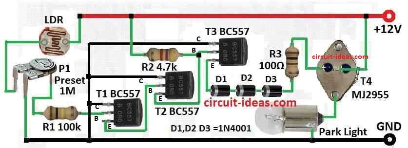
| Components | Values | Quantity |
|---|---|---|
| Resistors (All resistors are 1/4 watt) | 100k, 4.7k, 100Ω | 1 each |
| Preset 1M | 1 | |
| Semiconductors | Transistors BC557 | 3 |
| Transistor MJ2955 | 1 | |
| Diodes 1N4001 | 3 | |
| LDR | 1 | |
| Park light | 1 |
To begin with, this light sensor switch turn ON the park light when outside light goes down to some level; as this circuit is for PNP type which work with base that have positive ground.
Also, we can change when light turn ON by turning preset P1.
Formula:
Before using the formula it is very important to know how automatic parking light switch work, mostly it uses voltage divider and one light sensor like LDR or photoresistor.
Parking lights turn ON or OFF by checking voltage at one point in divider and compare with reference voltage.
Basic formula for voltage divider is:
Vout = Vin × (R2 / (R1 + R2))
where:
- Vout is voltage across R2 that is output voltage
- Vin input voltage which is mostly car battery
- R1 and R2 are two resistors in divider
In our circuit we have used formula:
Vout = Vin × (P1 / (LDR + P1))
How it Work in Circuit:
LDR is one resistor in this parking light switch circuit and this LDR change resistance when light change.
Furthermore, if light is low it means dark then LDR resistance will go high, then Vout also will go high and when Vout goes higher at a set level then parking lights turn ON.
If light is bright then LDR resistance will go low and then Vout also will go low and if Vout goes lower at a set point then parking lights stays OFF.
How to Build:
To build a Automatic Parking Light Switch Circuit follow the below mentioned steps:
Choose Right Transistor:
- First, pick one PNP transistor and choose it by checking it base type.
Connect LDR:
- Next, one side of LDR connects to transistor T1 base and other side connects to positive supply with one resistor.
Connect Preset:
- After that, one side of preset P1 connects to ground and other side connects to positive supply and middle pin wiper connects to transistor T1 base with one resistor.
Add Other Parts:
- Then connect transistor T4 emitter to positive and collector connects to parking light bulb.
- Now after making the circuit test it first and turn preset to set when light turn ON and light should turn ON when outside get dark to preset level.
Install in Car:
- Put circuit in car and connect all wires to right parts.
Note:
- Lastly, check component polarity and all wire connection two times, as wrong connection can stop circuit working.
Conclusion:
To conclude, Automatic Parking Light Switch Circuit is easy and useful, as it switches ON the car parking lights by itself when outside light goes low; also this give comfort and safety to driver.
Leave a Reply