Simple Battery Eliminator Circuit using IC LM317 gives steady DC power with no need of normal battery, as it is good for small devices needing stable voltage.
Furthermore, this article show how to make simple battery eliminator using LM317 IC and we can also show circuit to replace 9V battery and we use this circuit for any device which need 9V battery.
Circuit Working:
Parts List:
| Components | Quantity |
|---|---|
| Resistors | |
| 1.5k 1/4 watt | 1 |
| 220Ω 1/4 watt | 1 |
| 15k 1/4 watt | 1 |
| Capacitors | |
| Electrolytic 10µF 25V | 2 |
| Semiconductors | |
| IC LM317 | 1 |
| Diodes 1N4007 for bridge rectifier | 4 |
| Transformer 230V primary, 9V secondary 1.5A | 1 |
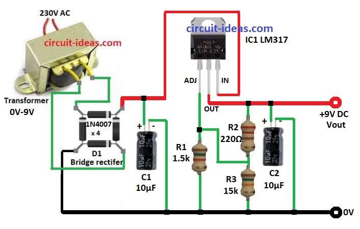
Transformer take 230V AC and change to 9V AC and then bridge rectifier with 4 diodes 1A each change AC to pulsating DC.
After that, capacitor C1 10μF filter this DC to make it better , then this DC goes to LM317 IC and give steady and adjustable voltage.
Output voltage depend on resistors R1 and R3, also another capacitor C2 10μF at output makes voltage more smooth and reduces the ripples.
Formulas:
Formula for LM317 Output Voltage:
Vout = Vref × (1 + R2 / R1)
where,
- Vref is 1.25V Iadj which is very small and can be skip
How to Build:
To build a Simple Battery Eliminator Circuit using IC LM317 follow the below mentioned steps:
- First, gather all the parts as shown in circuit diagram
- Next, connect (+) of C1 to input pin of IC1 and (–) of C1 to GND.
- After that, connect ADJ pin of IC1 to one side of R1 and other side of R1 to GND, ADJ pin also connect between R2 and R3.
- Then output pin of IC1 go to (+) of 9V DC and (–) goes to GND and also R2 and R3 connect from output pin to GND.
- Now positive of C2 connect to output pin of IC1 and negative of C2 connect to GND.
- Further, connect bridge rectifier one pin to input of IC1 and other pin to GN and third and fourth pins go to two wires of 9V transformer
Conclusion:
To conclude, this Simple Battery Eliminator Circuit using IC LM317 provides a stable DC voltage and works well for electronic devices that do not require a battery.
Also, IC LM317 keeps voltage steady and hence, this circuit is easy and simple and is best for beginners and hobby lovers.
Leave a Reply