Simple BFO circuit is small electronic circuit which make signal sound when mix with other signal; also this circuit help to hear weak radio signal like in old radio or metal detector.
Moreover, it is easy to build and uses one transistor part called a bipolar junction transistor (BJT).
What is Beat Frequency Oscillator:
BFOs are used to receive SSB (single sideband) and CW (continuous wave) signals and they generate a signal that mixes with the IF output from the detector and produces an AM signal.
Then detector remove this AM signal.
When mode switches and connects to ‘C’ or SSB then BFO turns ON.
Circuit Working:
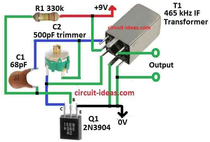
Parts List:
| Components | Values | Quantity |
|---|---|---|
| Resistor | 330k 1/4 W CFR | 1 |
| Capacitors | Ceramic 68pF | 1 |
| Trimmer 500pF | 1 | |
| Semiconductor | Transistor 2N3904 | 1 |
| Transformer 465 kHz IF | 1 |
This LC oscillator uses one BJT transistor for make BFO and this simple circuit and explanation show the following:
First, resistor R1 gives right power to BJT Q1 so it works good and also BJT collector connect to main coil of 465 kHz transformer L.
Then the second coil give feedback to keep oscillation going.
Also, transformer and variable capacitor C1 set the frequency like in Hartley oscillator.
To change the tuning, we remove the built-in capacitor of the transformer and use C1 instead and when we change the value of C1, the frequency also changes.
Furthermore, the BJT collector provides the output signal and we can use this signal to enhance the beat frequency.
Also, output frequency goes from 465 kHz to 1.7 MHz by moving C1 and this setup gives easy way to make signal in that range.
Finally, we can change parts to fit what we need by testing and adjusting the values.
Formulas:
We find the frequency f of the LC oscillator using this formula for a Hartley oscillator:
f = 1 / 2π√(L × C)
where:
- f is frequency in hertz Hz.
- 2π means 2 times pi, where pi is approximately 3.14159 and we use it in many wave and signal formulas.
- L is inductance of coil in henries H where coil stops fast to change in current.
- C is capacitance of capacitor in farads F where capacitor store energy in electric field.
- √ means square root.
This formula says if L or C become big then frequency f become small, so more capacitance or more inductance = lower frequency.
Less capacitance or inductance = higher frequency.
How to Build:
Below mentioned are the building steps for Simple Beat Frequency Oscillator (BFO) Circuit:
Bias in Transistor:
- First, be sure BJT have correct bias to work stable and to put it in right setup.
- Then one tuned 465 kHz transformer connect to transistor Q1 collector.
Transformer Setup:
- Also, use normal Hartley oscillator setup with this transformer.
- Main coil and feedback coil must connect in correct way to start oscillation.
Tuning Control Change:
- After that, remove transformers own tuning capacitor and then use variable capacitor C1 to change frequency.
Frequency Range Change:
- Move C1 to change output frequency which can go from 465 kHz to 1.7 MHz.
Uses:
- Also, place a nearby radio that can receive normal broadcast signals to check the frequency.
- Make beat sound by setting generator to radios IF intermediate frequency and this will help hear SSB single sideband or CW continuous wave signals.
Conclusion:
Overall, engineers and hobby people can build this Simple Beat Frequency Oscillator (BFO) Circuit easily.
Moreover, it has wide frequency range and can work as BFO or local oscillator; also rhis circuit is good for testing or using in actual circuit.
Leave a Reply