FM mic transmitter is small device and it changes sound from mic into radio signal.
FM radio can hear it in short distance and this Simple FM Microphone Transmitter Circuit uses one NPN BC547 transistor., even it is small it can send FM signal pretty far.
Circuit Working:
Parts List:
| Components | Values | Quantity |
|---|---|---|
| Resistors | 330Ω 1/4 watt | 1 |
| 4.7k 1/4 watt | 1 | |
| Capacitors | Ceramic 0.001μF | 1 |
| Ceramic 22pF | 1 | |
| Trimmer capacitor | 1 | |
| Semiconductors | BC547 | 1 |
| Inductor coil 0.1uH | 1 | |
| Antenna | 1 | |
| Electret mic | 1 | |
| Battery 9V | 1 |
To begin with, this FM transmitter circuit take voice from small mic means condenser mic and if we want to send direct audio then remove mic and give audio at base and R1 point.
Then to make signal go more far then use long wire or antenna.
After that, trim capacitor C2 and coil L1 set the FM signal frequency and always use free non-commercial FM band and with this simple FM transmitter we can send sound on FM radio.
Easy points about this circuit:
One Transistor Only:
It is for very simple use only with one transistor.
Changeable Frequency:
Also, by adjusting C1 and L1 we can change frequency from 50MHz to 160MHz where FM radio can catch it.
Mic Input:
Mic take sound and circuit makes signal.
Furthermore, use small battery power with only few parts inside which is not as strong or clear as advanced circuits but is good for beginners to learn FM transmitter basics.
Formulas:
We can find the exact working frequency of FM transmitter using this formula:
f = 1 / (2π√(L * C))
where:
- f is frequency in hertz Hz
- L is coil value in henrys H
- C is capacitor value in farads F
Note:
Hence, this formula works for perfect circuit and in real life small extra things like wire effects or part changes can change result a bit.
Additionally, the trimmer capacitor C2 allows us to adjust the frequency within the FM broadcast band of 88 MHz to 108 MHz.
Therefore, when building an FM microphone transmitter, use the complete circuit diagram with all component values and follow the recommended tuning tips to achieve the desired frequency and stable operation.
How to Build:
To build a Simple FM Microphone Transmitter Circuit follow the below mentioned steps for connections:
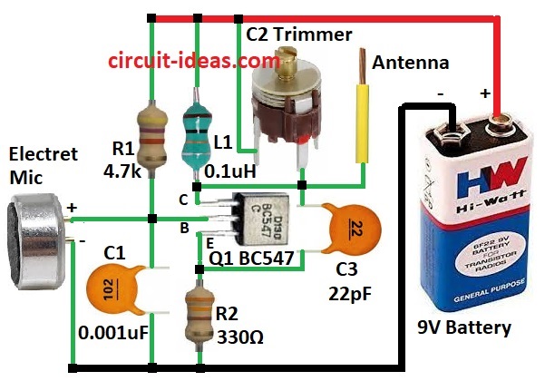
- First, gather all parts like in circuit diagram.
- Next, connect collector of transistor Q1 to +9V battery through coil L1, connect base of Q1 to (+) side of electret mic and connect (–) side of mic to ground and also connect emitter of Q1 to ground through resistor R2.
- Then connect R1 and C1 from +9V to ground and also connect capacitor C2 between +9V and collector of Q1.
- Attach antenna after C2 and also connect C2 between collector of Q1 and point between emitter and R2.
Important Notes:
- FM mic transmitters must follow our countries radio rules and we must use only allowed power and frequency.
- Ask the local radio department for legal information.
Conclusion:
To conclude, this Simple FM Microphone Transmitter Circuit is great for learning how FM signals work, but always be safe and follow the local radio laws.
Leave a Reply